blindrezo wrote:
Hey guys,
Just wanted to let you all know that my brother and I managed to successfully mod the player. Works like a charm!
Many thanks, once again, to all those that helped make this happen.
Just wanted to let you all know that my brother and I managed to successfully mod the player. Works like a charm!
Many thanks, once again, to all those that helped make this happen.
great'
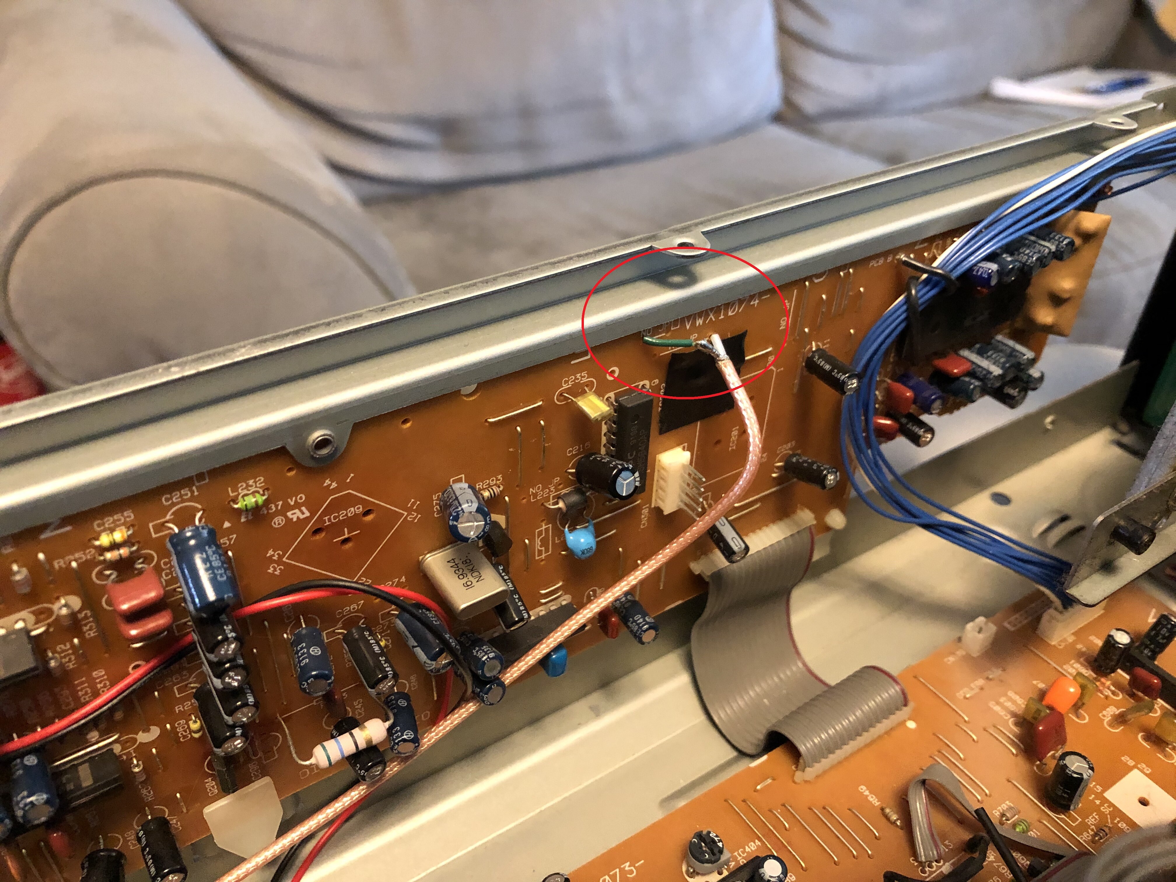
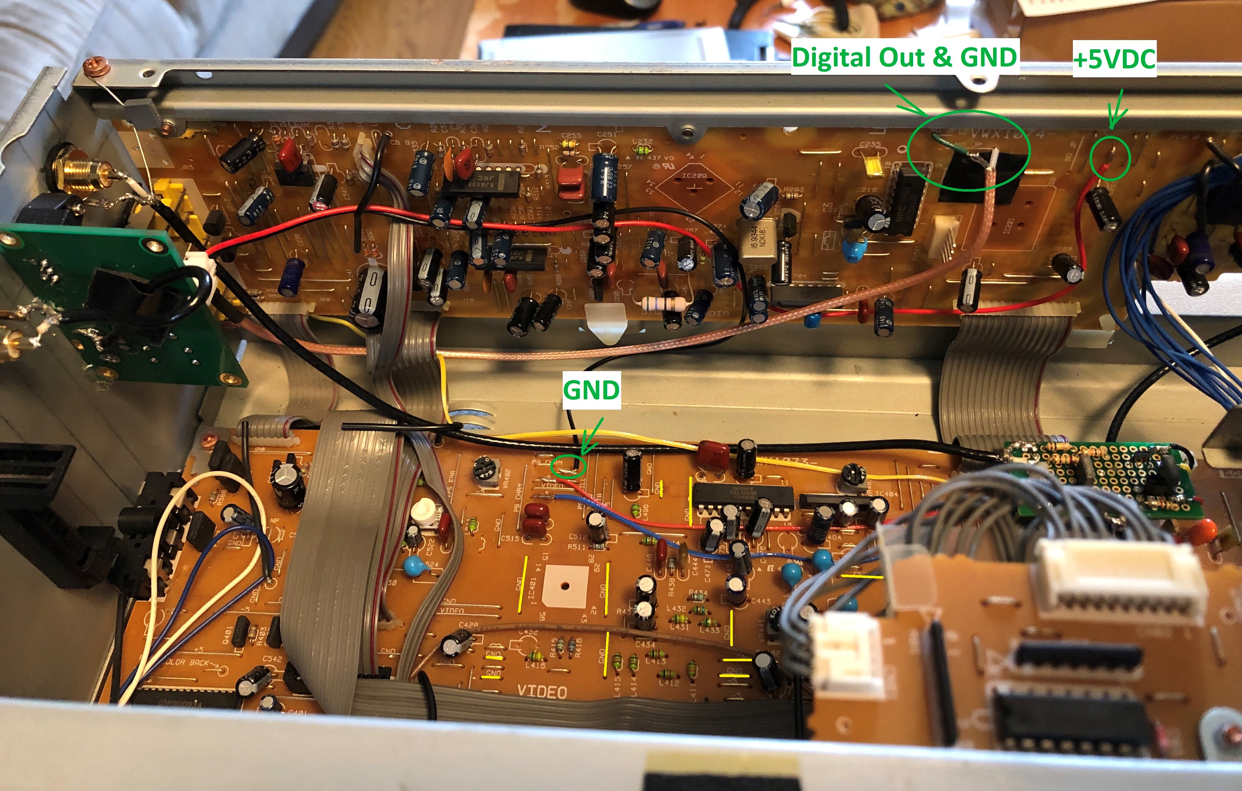
I have succesfully installed the boards from ebay. I ussually remove the optical output.
This photo is a cld-d515 with a part cut of the backpanel coming from a donor player I did years ago.
I only soldered in the missing components on the original main board
| Attachments: |
|
23795236_188651835027319_186956708409422876_n resized.jpg [ 34.3 KiB | Viewed 1839 times ] |