ldfan wrote:
There appears to be two mute points located on connector CN16, pin 9 or connector CN18, pin 6 on the AUDB board but not sure which one works (or neither). You can easily test the points by placing a voltmeter on it and see if the volts go from 0vdc to 5vdc (or vice versa) when going from pause & play. Whichever way the volts go will depend if you need to make an AC3 board for Mute Active High (MAH) or Mute Active Low (MAL). So when the player is in pause/stop mode & the voltage is +5vdc, that is MAH. MAL will be the reverse.
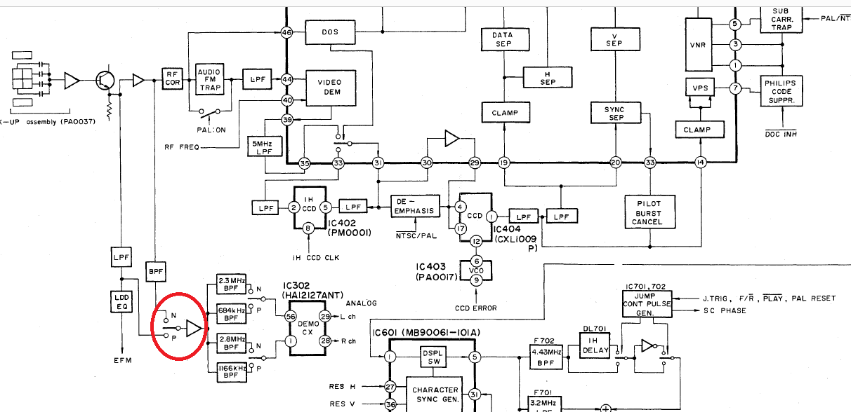
For the RF tap, that is tougher to find but there is a logic to it. You need to locate the CX chip which is IC302 and place the RF cable somewhere before the band pass filters. Here is a snapshot of the service manual showing in red approximately where it would be....
And here is an example of where I tapped the RF point on my CLD-M90....
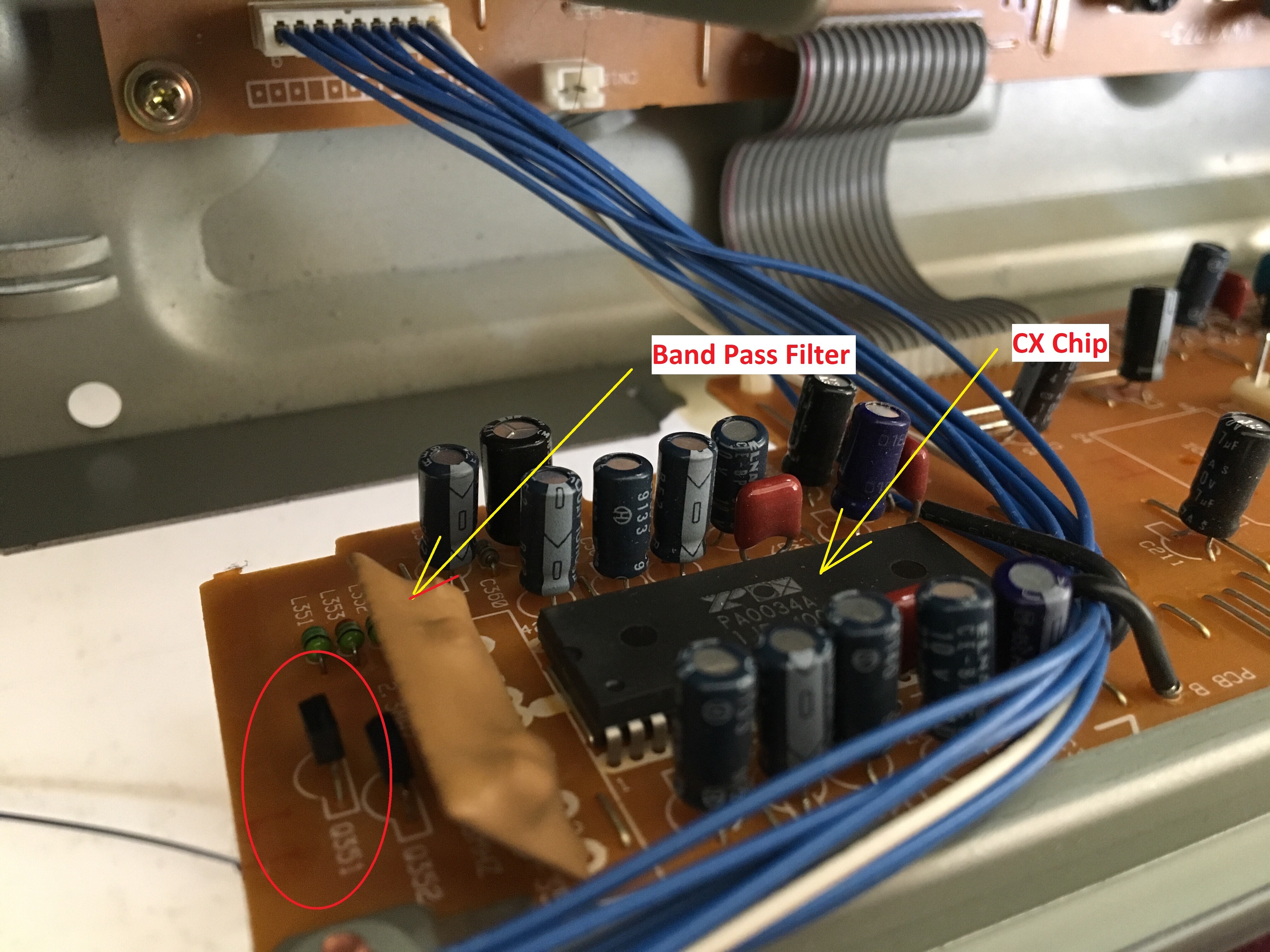
The point I chose was the middle pin of transistor Q351 but I think it would have worked on just about any of the legs of the two transistors located there as it doesn't have to be exact.
Keeps us posted on what you find and good luck.

Did not find the time nor had the drive to start experimenting with the rf tap myself.
Sold all the 4400 last year since I had way too much around.
Came to realize you just can’t own them all

Must say these are very reliable players built to last forever. Sold them to local people who use em with great pleasure these days and that is what they should be doing anyway… put into good use
2 of these players went to Holland. Fellow is adding ac-3 and hdmi out ( just because he can is what he told me )
It all went to a good home in the end
Thank you for the advice ld fan

