|
It is currently 24 Apr 2024, 11:19
|
View unsolved topics | View unanswered posts
 |
|
 |
|
| Author |
Message |
|
kris
|
Post subject: [LD-V4400] AC3RF Mod  Posted: 19 Apr 2019, 07:08 |
| Hardcore fan |
 |
 |
Joined: 05 Dec 2006, 19:08
Posts: 1181
Location: Belgium
Has thanked: 47 times
Been thanked: 32 times
|
Belgian market got flooded by a massive ammount of LD-v4400 players. Got 6 myself   now for the hard part... Upgrade these to "modern" output connections... AC-3rf & dts out Any ideas where to begin?
CLD-D925
RFD-1
CLD-99 elite
Lexicon LDD-1
SR-7015
RMB-1585
DP-UB820
TX-58DX780E
|
|

|
|
 |
|
ldfan
|
Post subject: Re: LD-V4400 Posted: 20 Apr 2019, 08:50 |
| Hardcore fan |
|
 |
Joined: 28 Jun 2014, 05:59
Posts: 1459
Location: San Francisco, CA USA
Has thanked: 425 times
Been thanked: 533 times
|
It obviously starts w/ needing points for the player to do either of the mods. For AC3-RF, I assume the 4400 is very similar to the 4300 (don't hold me to it; just guessing since they look very similar) of which we have the service manual available here.... http://manuals.lddb.com/LD_Players/Pion ... LD-V4300D/If you go to page 16 of the pdf, it appears to show where many of the points for the mod are located (e.g.: RF, +5V, -5V, and GND are located on connector CN1 and Mute appears to be on connector CN16 or CN18). Not sure if this 4400 is a Mute Active High (MAH) or Mute Active Low (MAL) player since it appears to be a PAL capable machine which are usually MAL (this makes a difference since a mod board needs to be built for either design). Once you know that information, then you need to build the AC3-RF board. This is the version I made for my Pro-Scan player... Scratch built AC3-RF board installed in my ProScan, PSLD43This board is made specifically for an MAH player. Moving on to the S/PDIF output, you can buy a kit from ebay to make this job easier but you'll still need to get the information on where the digital output resides in the player. Once again, going back to the service manual, page 24 of the manual shows the AudB board and the digital output appears to be located on IC-306, pin 60 (DOUT). You'll also need to verify if pin 59 (MD2) is pushing 5VDC as this indicates if the digital output is switched on for the chip (a reading of 0VDC means it's off but I believe you just need to jump 5v to it to get it turned on). Anyway... here is the digital output kit that I will be using for my digital out mod on my CLD-M90.... https://www.ebay.com/itm/CDROM-car-navi ... 1ec39ea35bHope this helps and best of luck. |
|
|
|
|
|
|
kris
|
Post subject: Re: LD-V4400 Posted: 24 Apr 2019, 13:46 |
| Hardcore fan |
|
|
Joined: 05 Dec 2006, 19:08
Posts: 1181
Location: Belgium
Has thanked: 47 times
Been thanked: 32 times
|
takeshi666 wrote: Do multi-standard LD-V4400s even exist? Wouldn't Belgian ones then just be PAL only?
In which case this'd be a pointless endeavour? they are NTSC only units running 120volts. Great PQ but they lack outputs so...
CLD-D925
RFD-1
CLD-99 elite
Lexicon LDD-1
SR-7015
RMB-1585
DP-UB820
TX-58DX780E
|
|
|
|
|
|
|
kris
|
Post subject: Re: LD-V4400 Posted: 24 Apr 2019, 19:00 |
| Hardcore fan |
|
|
Joined: 05 Dec 2006, 19:08
Posts: 1181
Location: Belgium
Has thanked: 47 times
Been thanked: 32 times
|
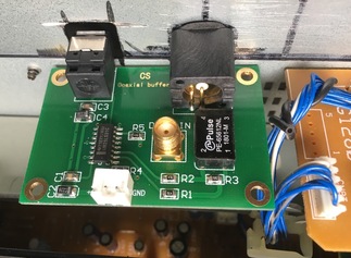
ldfan wrote: It obviously starts w/ needing points for the player to do either of the mods. For AC3-RF, I assume the 4400 is very similar to the 4300 (don't hold me to it; just guessing since they look very similar) of which we have the service manual available here.... http://manuals.lddb.com/LD_Players/Pion ... LD-V4300D/If you go to page 16 of the pdf, it appears to show where many of the points for the mod are located (e.g.: RF, +5V, -5V, and GND are located on connector CN1 and Mute appears to be on connector CN16 or CN18). Not sure if this 4400 is a Mute Active High (MAH) or Mute Active Low (MAL) player since it appears to be a PAL capable machine which are usually MAL (this makes a difference since a mod board needs to be built for either design). Once you know that information, then you need to build the AC3-RF board. This is the version I made for my Pro-Scan player... Scratch built AC3-RF board installed in my ProScan, PSLD43This board is made specifically for an MAH player. Moving on to the S/PDIF output, you can buy a kit from ebay to make this job easier but you'll still need to get the information on where the digital output resides in the player. Once again, going back to the service manual, page 24 of the manual shows the AudB board and the digital output appears to be located on IC-306, pin 60 (DOUT). You'll also need to verify if pin 59 (MD2) is pushing 5VDC as this indicates if the digital output is switched on for the chip (a reading of 0VDC means it's off but I believe you just need to jump 5v to it to get it turned on). Anyway... here is the digital output kit that I will be using for my digital out mod on my CLD-M90.... https://www.ebay.com/itm/CDROM-car-navi ... 1ec39ea35bHope this helps and best of luck. Have this board around coming from a dvl-700... everything is there I think
| Attachments: |

IMG_6621.JPG [ 131.03 KiB | Viewed 6610 times ]
|
_________________
CLD-D925
RFD-1
CLD-99 elite
Lexicon LDD-1
SR-7015
RMB-1585
DP-UB820
TX-58DX780E
|
|
|
|
|
|
|
ldfan
|
Post subject: Re: LD-V4400 Posted: 24 Apr 2019, 22:34 |
| Hardcore fan |
|
|
Joined: 28 Jun 2014, 05:59
Posts: 1459
Location: San Francisco, CA USA
Has thanked: 425 times
Been thanked: 533 times
|
kris wrote:
Have this board around coming from a dvl-700... everything is there I think
I think this board is from a DVL-909 which has the two coax S/PDIF, one optical S/PDIF, and one AC3-RF. In any case, I don't think this one would work because the board is integrated for all three types of connections and I would not know how that connector is wired up to handle all these different connections (in fact, the connector may go to something further down the line that processes more info so you might have to transplant that part as well to the 4400). Either way, better to just build a dedicated AC3-RF board and get a S/PDIF kit; either a generic one on ebay or transplant one from another Pioneer player that has a coax out. The Pioneer, CLD-59 and CLD-D702 do have S/PDIF coax boards that can be easily integrated into other players. Here is the board from the CLD-59 (note that it connects back to a part of the main board that would have been the optical output on a CLD-D604)....  |
|
|
|
|
|
|
kris
|
Post subject: Re: LD-V4400 Posted: 27 Apr 2019, 09:18 |
| Hardcore fan |
|
|
Joined: 05 Dec 2006, 19:08
Posts: 1181
Location: Belgium
Has thanked: 47 times
Been thanked: 32 times
|
ldfan wrote: kris wrote:
Have this board around coming from a dvl-700... everything is there I think
I think this board is from a DVL-909 which has the two coax S/PDIF, one optical S/PDIF, and one AC3-RF. In any case, I don't think this one would work because the board is integrated for all three types of connections and I would not know how that connector is wired up to handle all these different connections (in fact, the connector may go to something further down the line that processes more info so you might have to transplant that part as well to the 4400). Either way, better to just build a dedicated AC3-RF board and get a S/PDIF kit; either a generic one on ebay or transplant one from another Pioneer player that has a coax out. The Pioneer, CLD-59 and CLD-D702 do have S/PDIF coax boards that can be easily integrated into other players. Here is the board from the CLD-59 (note that it connects back to a part of the main board that would have been the optical output on a CLD-D604).... Did transplant an rf board coming from a cld-d515 once into a cld-2950 that worked like a charm. Getting a dedicated board for dts out. They are dead cheap and it shouldn't be hard putting it in .
CLD-D925
RFD-1
CLD-99 elite
Lexicon LDD-1
SR-7015
RMB-1585
DP-UB820
TX-58DX780E
|
|
|
|
|
|
|
ldfan
|
Post subject: Re: LD-V4400 Posted: 07 May 2019, 00:43 |
| Hardcore fan |
|
|
Joined: 28 Jun 2014, 05:59
Posts: 1459
Location: San Francisco, CA USA
Has thanked: 425 times
Been thanked: 533 times
|
kris wrote: Need to check if pin 59 needs the 5 volt. In most cases I would think it’s already powered as my CLD-M90 is powered already. Just make sure to use a voltmeter in continuity mode to trace out from pin 59 and then take the measurement from where a larger pin is located on the board (just to avoid shorting out the chip). kris wrote: Curious to see the boards arrive. The cable would be included. Fair price for a decent boards. Haven’t used mine yet but i’m sure it will work fine. I’m probably going to use a different RCA jack for my mod as I don’t like the size of the one provided. Also, trying to figure out a method to cut out a square opening so I can also run the optical output. And yes, the coax cable is included. |
|
|
|
|
|
|
ldfan
|
Post subject: Re: LD-V4400 Posted: 11 May 2019, 19:09 |
| Hardcore fan |
|
|
Joined: 28 Jun 2014, 05:59
Posts: 1459
Location: San Francisco, CA USA
Has thanked: 425 times
Been thanked: 533 times
|
Nice optical output mod.  At first I thought it was a factory output and then I noticed the back panel was transplanted. I wouldn't mind doing something like this for my M90 mod but I don't have any spare parts like that lying around. When I get a chance to start on my mod, I'll create a detailed post on it. Good to know that your digital out on the chip will work on the LD-V4400. |
|
|
|
|
|
|
kris
|
Post subject: Re: LD-V4400 Posted: 16 May 2019, 20:57 |
| Hardcore fan |
|
|
Joined: 05 Dec 2006, 19:08
Posts: 1181
Location: Belgium
Has thanked: 47 times
Been thanked: 32 times
|
The tricky part was soldering the wire for digital to the IC chip. It took me some trial and error on an old board I had around. The 4400 is an easy player to work on. Simply remove the bottom panel and you have clear acces to the boards. It is all there without removing one single wire or board. 5 volt and ground are straightforward to find. The IC chip is also very easy to acces. It is soldering it that takes a fast and steady hand. Many thanks for your help Ldfan. You did the research even before I had a manual 
| Attachments: |
IMG_2256.JPG [ 50.26 KiB | Viewed 6409 times ]
|
_________________
CLD-D925
RFD-1
CLD-99 elite
Lexicon LDD-1
SR-7015
RMB-1585
DP-UB820
TX-58DX780E
|
|
|
|
|
|
|
ldfan
|
Post subject: Re: LD-V4400 Posted: 17 May 2019, 00:50 |
| Hardcore fan |
|
|
Joined: 28 Jun 2014, 05:59
Posts: 1459
Location: San Francisco, CA USA
Has thanked: 425 times
Been thanked: 533 times
|
Wow... you work fast  . And nice work on the mod. I like the way you implemented the back panel; gives me some ideas for my upcoming mod. Hope you didn’t actually try to solder the wire directly to the leg of the chip for the digital output. If so, that’s much harder. I always look for a bigger point that makes continuity with the pin on a chip. |
|
|
|
|
|
|
kris
|
Post subject: Re: LD-V4400 Posted: 17 May 2019, 11:07 |
| Hardcore fan |
|
|
Joined: 05 Dec 2006, 19:08
Posts: 1181
Location: Belgium
Has thanked: 47 times
Been thanked: 32 times
|
Soldered it straight to the leg  Didn’t investigate the signal path but the next one I’ll do that. Not sure if it does have a signal path actually  It was trial and error soldering on a scrap board to get the hang of it.
Last edited by kris on 23 Jan 2020, 20:03, edited 1 time in total.
_________________
CLD-D925
RFD-1
CLD-99 elite
Lexicon LDD-1
SR-7015
RMB-1585
DP-UB820
TX-58DX780E
|
|
|
|
|
|
|
ldfan
|
Post subject: Re: LD-V4400  Posted: 18 May 2019, 03:55 |
| Hardcore fan |
|
|
Joined: 28 Jun 2014, 05:59
Posts: 1459
Location: San Francisco, CA USA
Has thanked: 425 times
Been thanked: 533 times
|
kris wrote: Soldered it straight to the leg Didn’t investigate the sihnal path but the next one I’ll do that. Not sure if it does have a signal path actually It was trial and error soldering on a scrap board to get the hang of it. As long as you did not damage it, you should be good. In any case, most larger chips (especially from yesterday's electronics) will have an obvious signal path that is usually easy to follow with a good eye and a voltmeter set to continuity mode to verify the path. Here is an example of the DSP chip off of my CLD-M90....  It makes it so much easier to solder to the pin that my voltmeter probe is touching in the pic.  |
|
|
|
|
|
|
|
 |
|
 |
|
You cannot post new topics in this forum
You cannot reply to topics in this forum
You cannot edit your posts in this forum
You cannot delete your posts in this forum
You cannot post attachments in this forum
|
|

