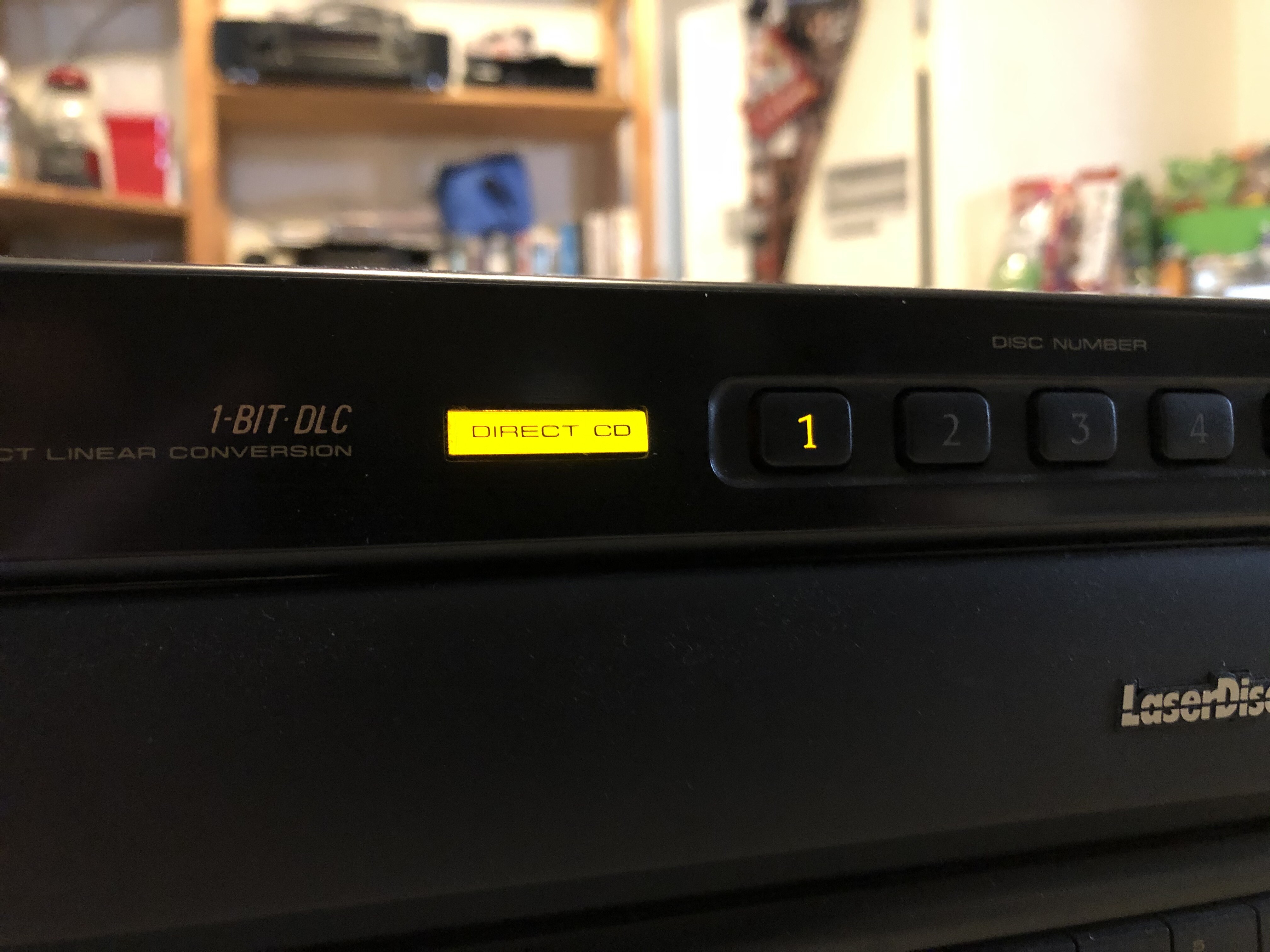
Hey everyone,
After saying for so long that I was going to do it, I finally found the time to complete this pretty intricate modification to this player. Let's quickly check out the before and after pics and then I'll provide some additional details.
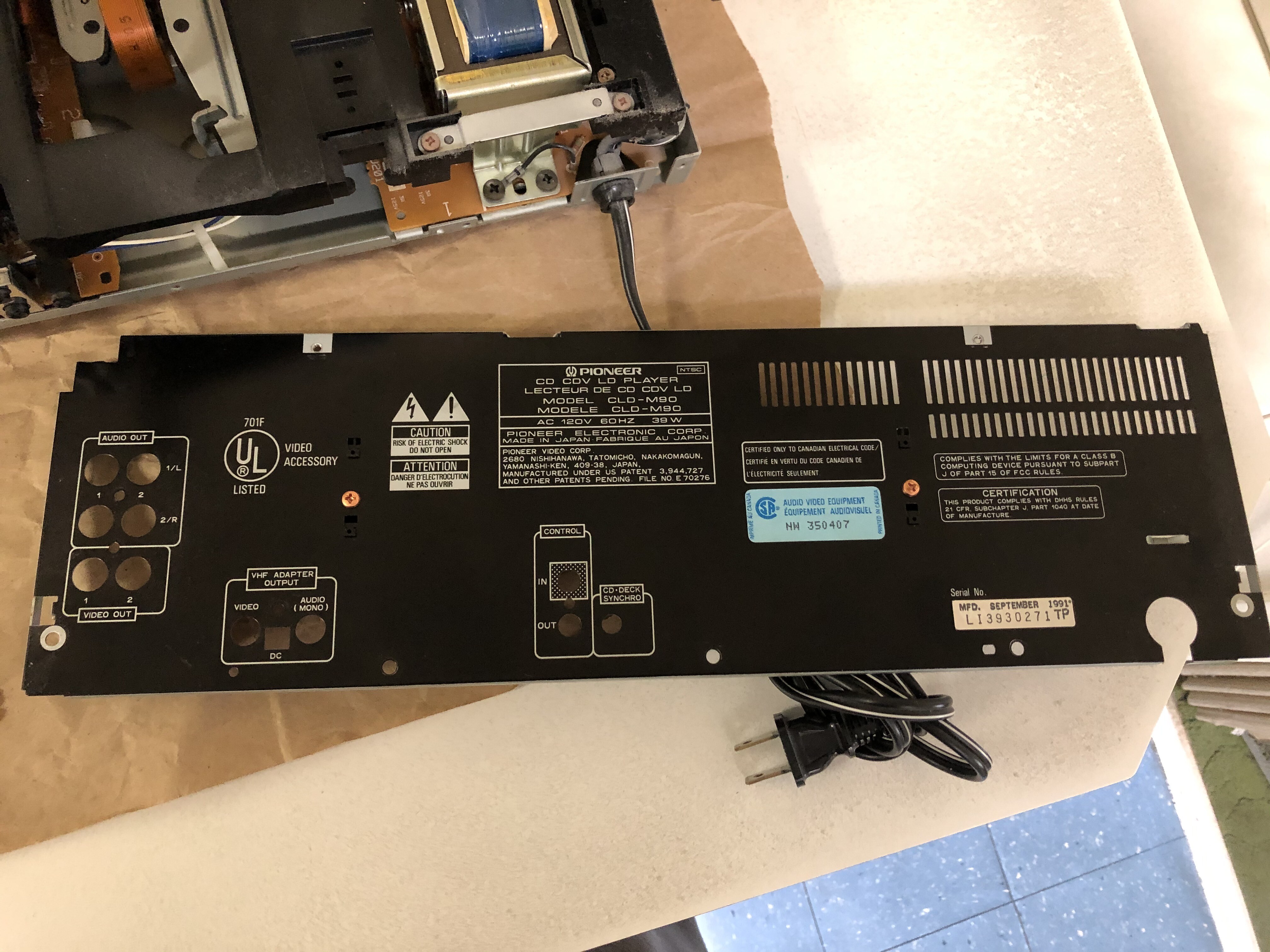
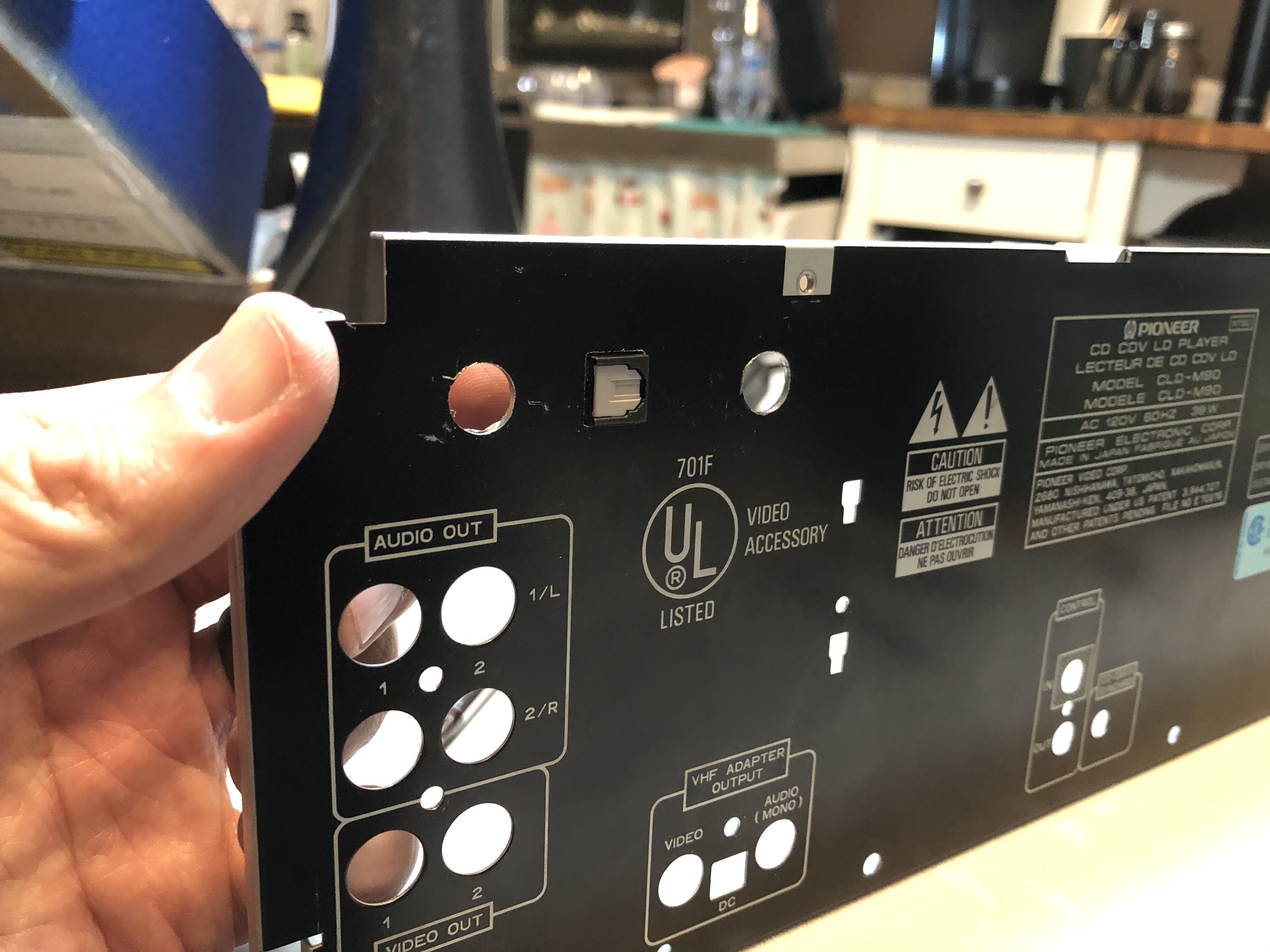
Front View Of The Player Back Panel "Before"
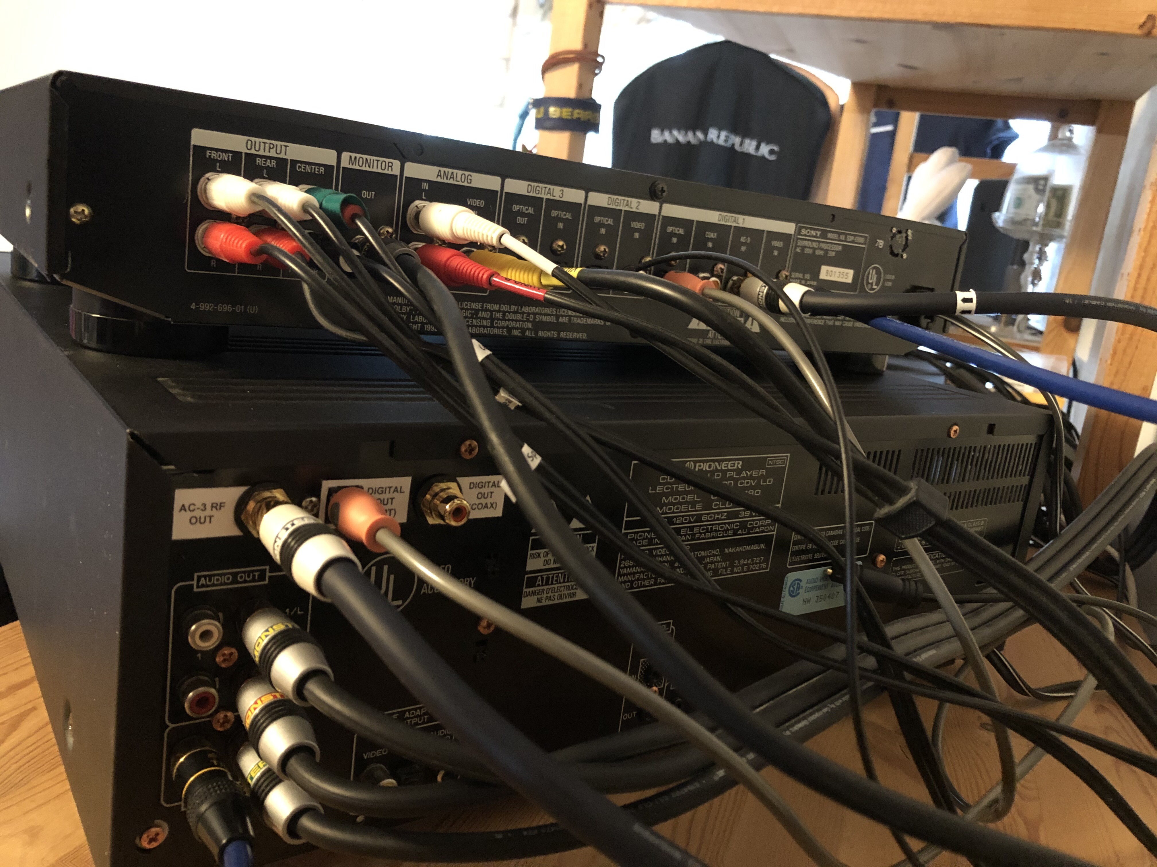
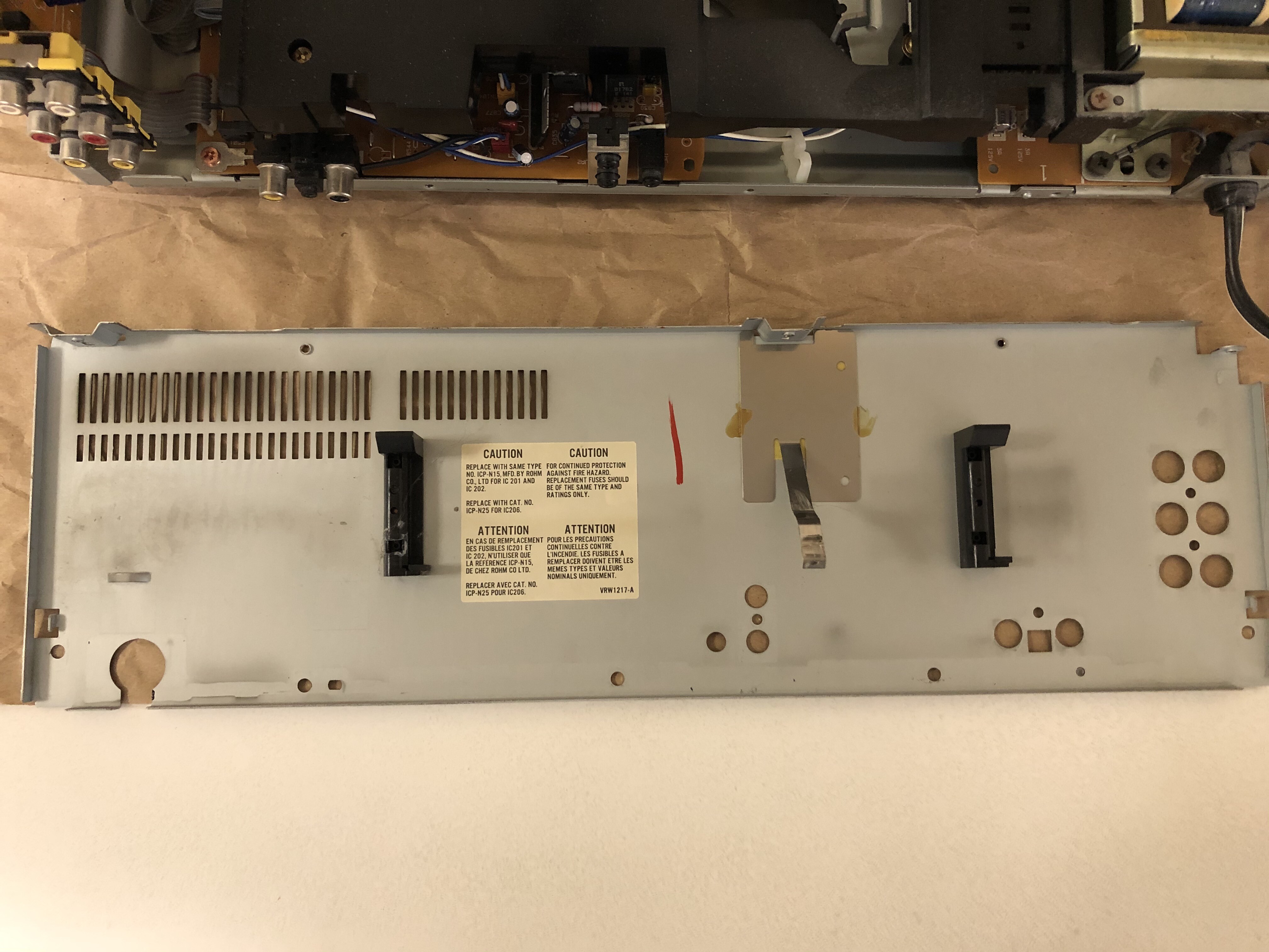
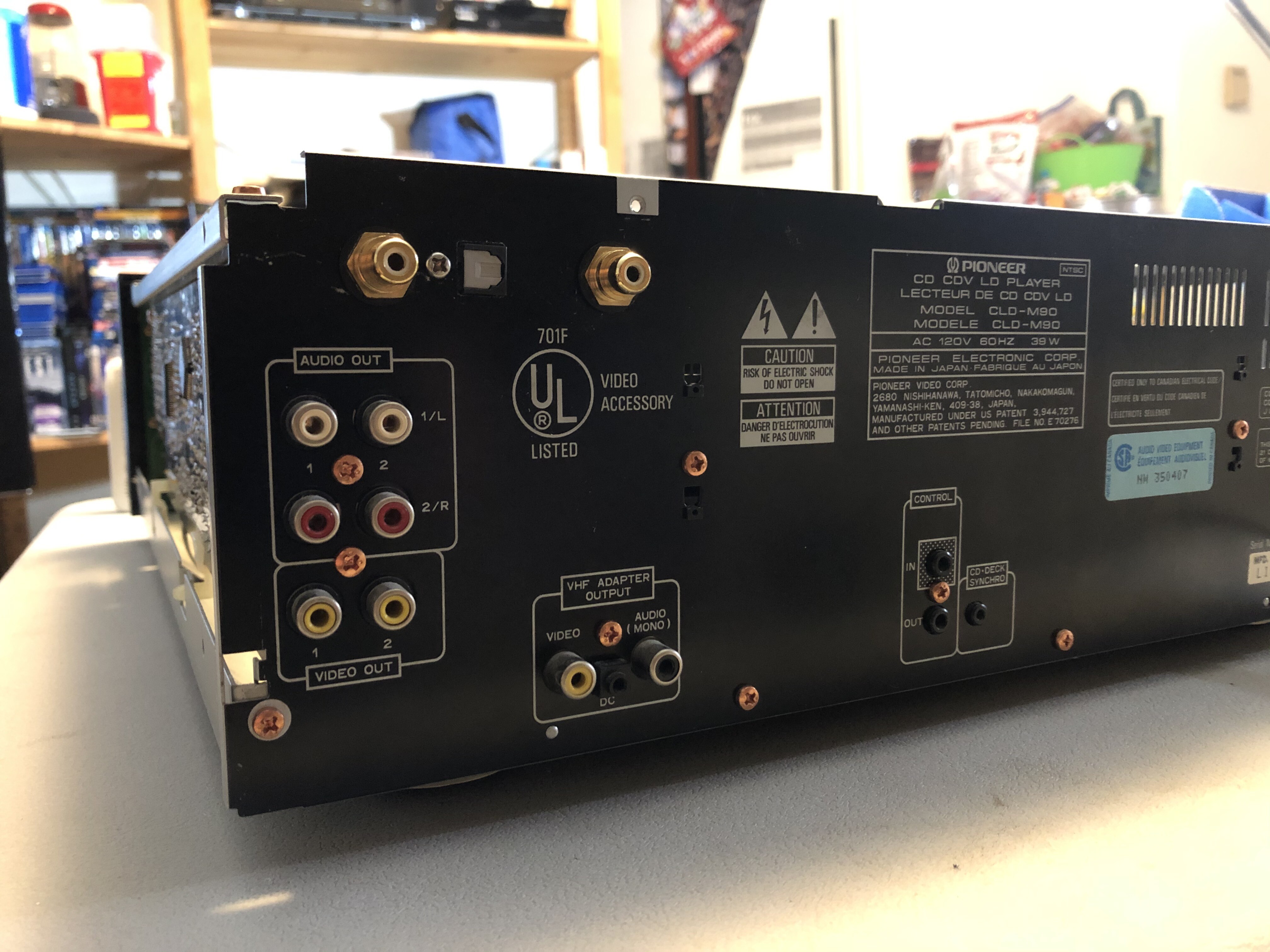
 Back Panel "After"
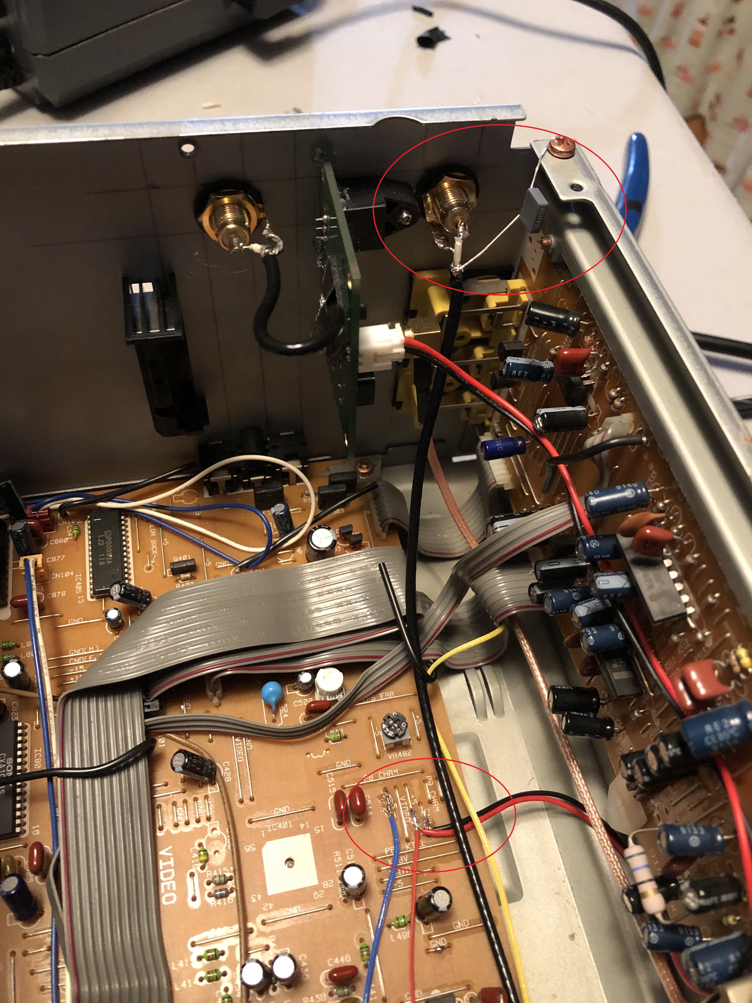
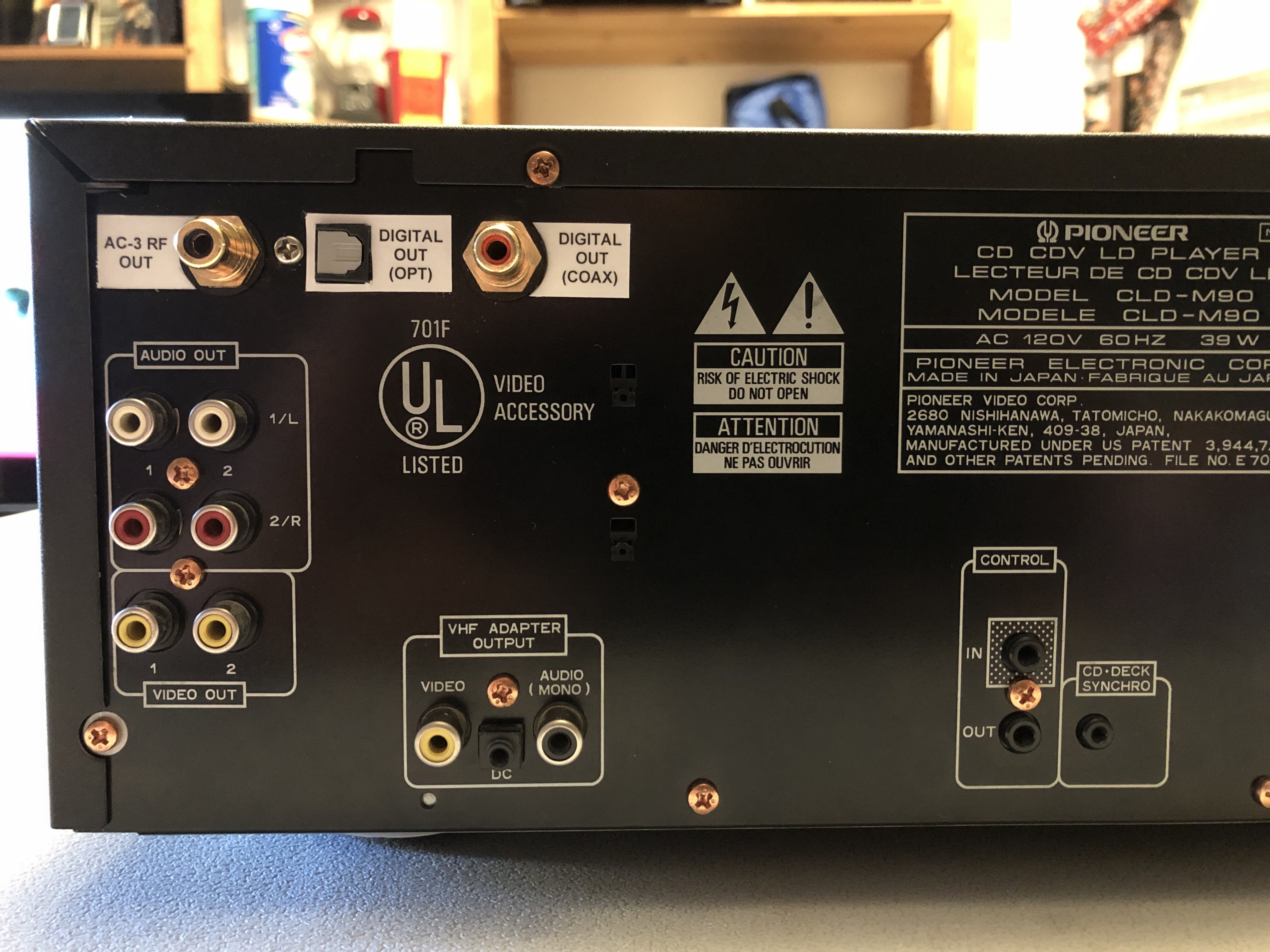 Back Panel "After" (wide view)
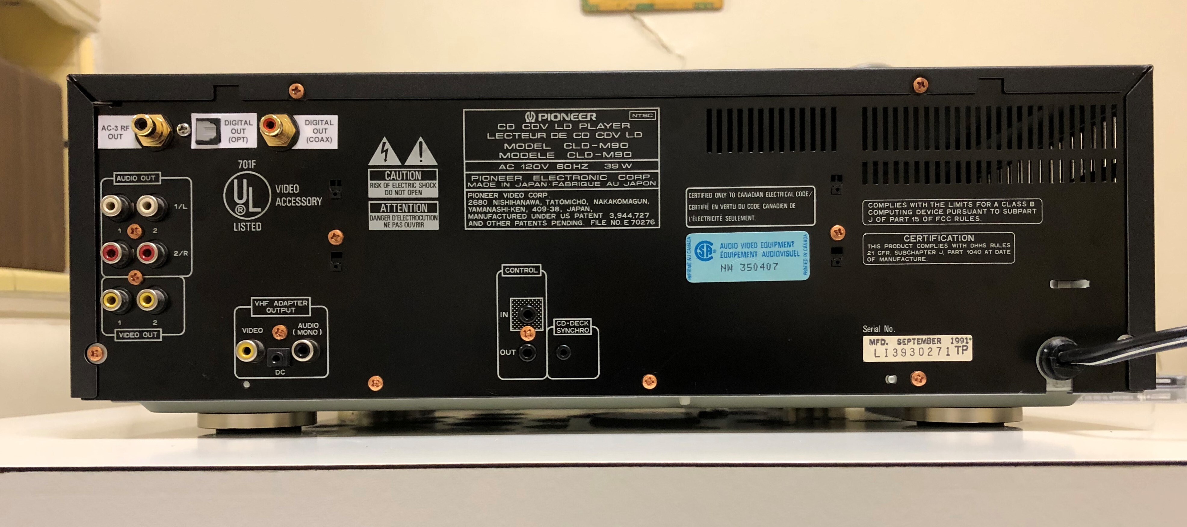 Back Panel "After" (side view)
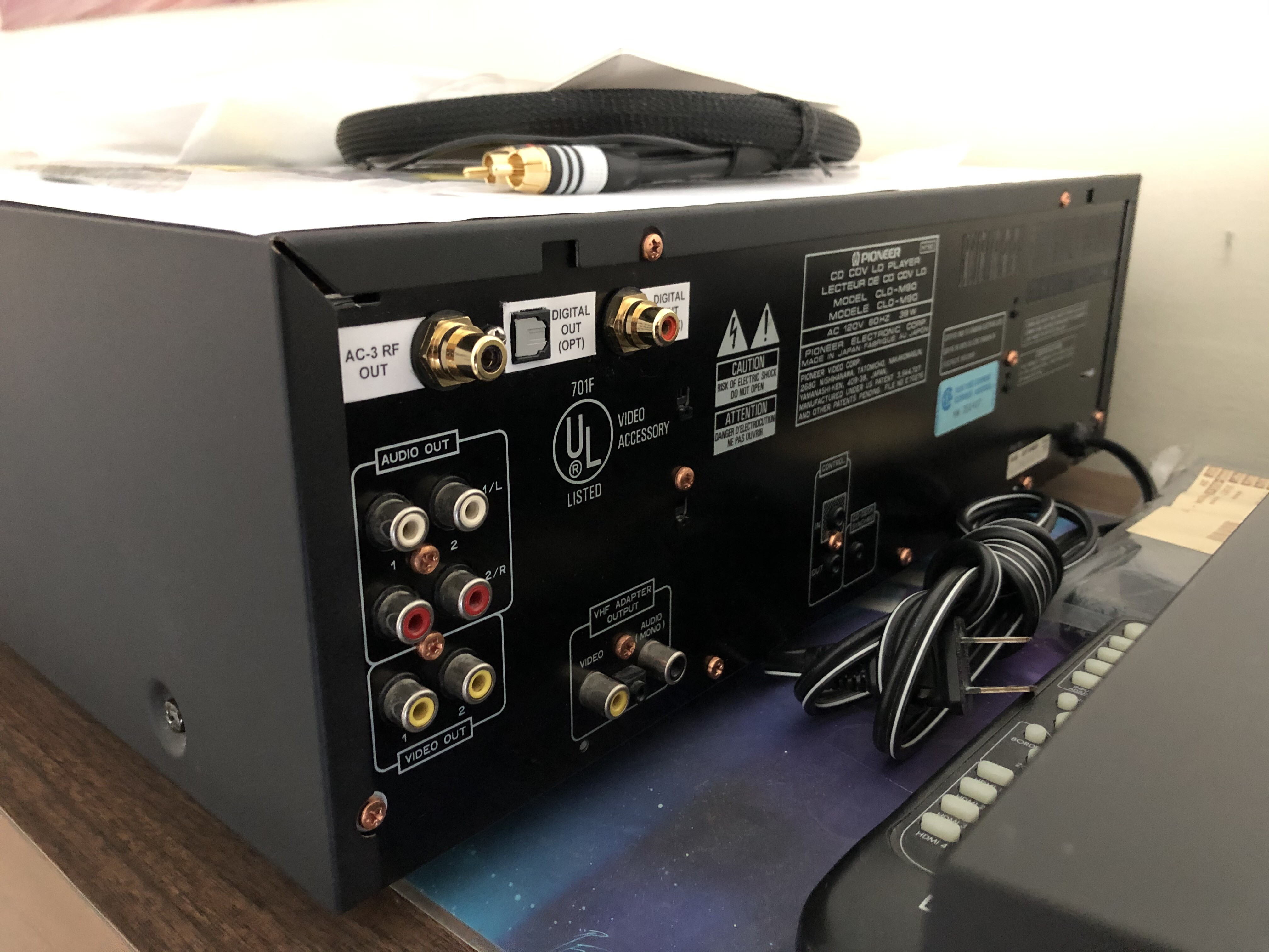
So now I'll break this mod down into four sections; 1) Back Panel Preparation, 2) Digital Output Mod, 3) AC-3 RF Output Mod, and 4) Adding Labels To The New Output Jacks.
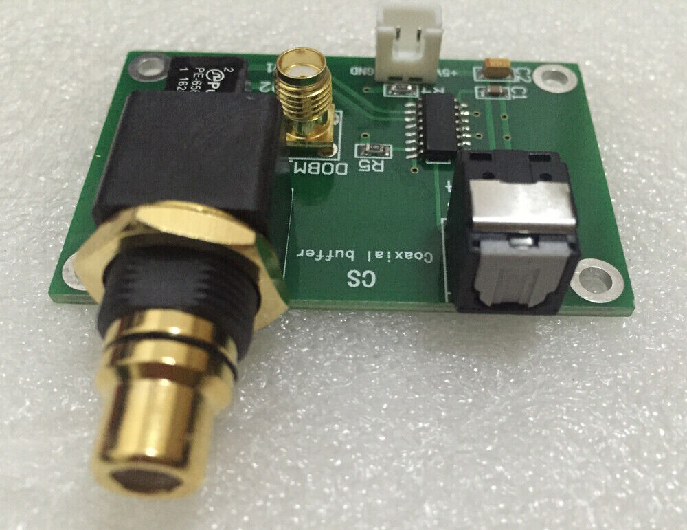
Back Panel Preparation:The first major challenge that literally took over a year to think about was how to punch out a square hole for the optical version of the Digital Output. I actually considered just doing the coaxial version of the Digital Output to simplify the mod but I really didn't want to waste the optical option that was part of the kit that I purchased. Here is the board that I used for this mod (
https://www.ebay.com/itm/CDROM-car-navi ... 3774426627 ).
I also considered just mounting this board simply "anywhere" inside the player and running a permanent optical cable out of a simple punch out but I thought it would look really cheesy (glad I did not do it).
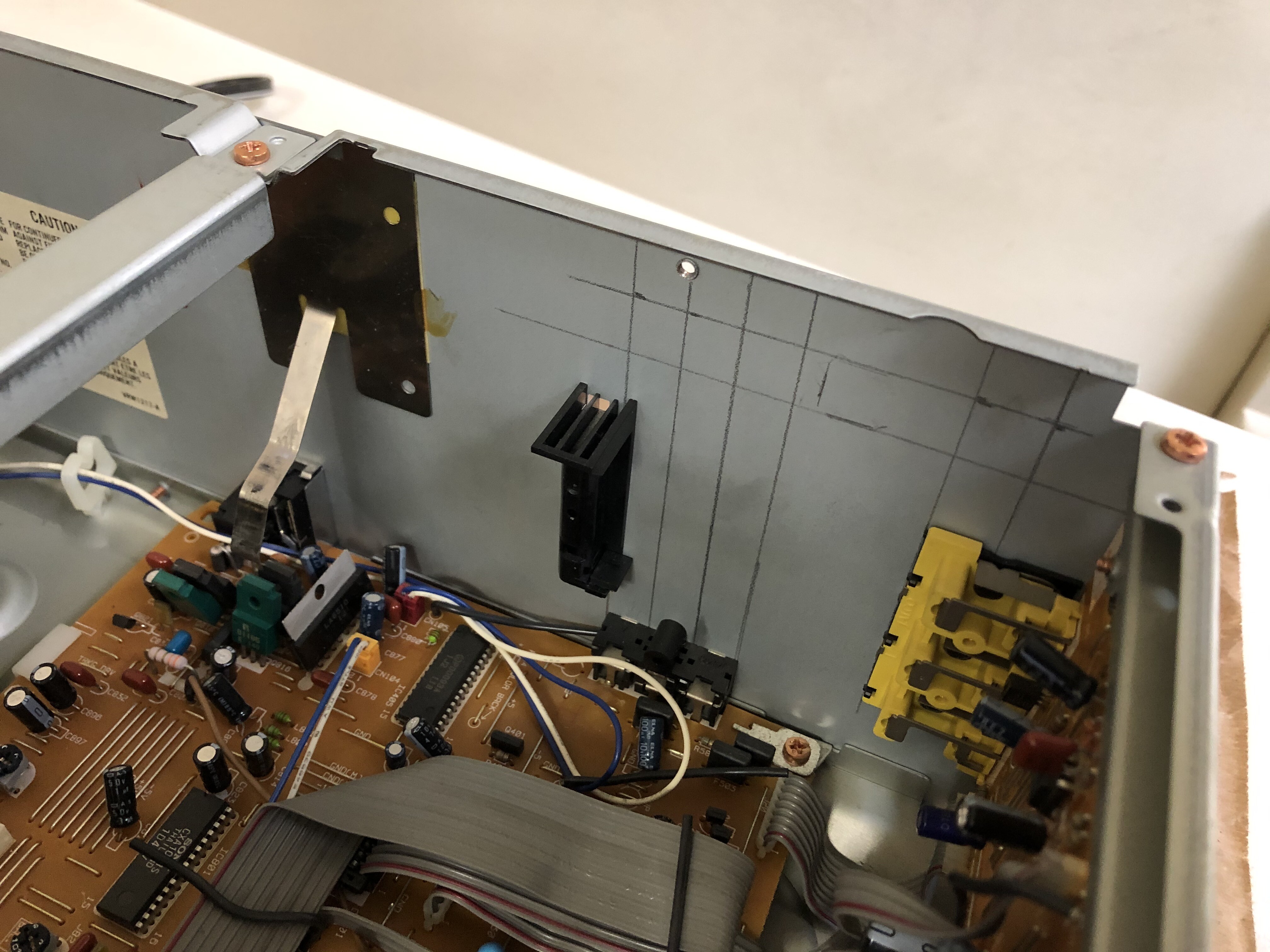
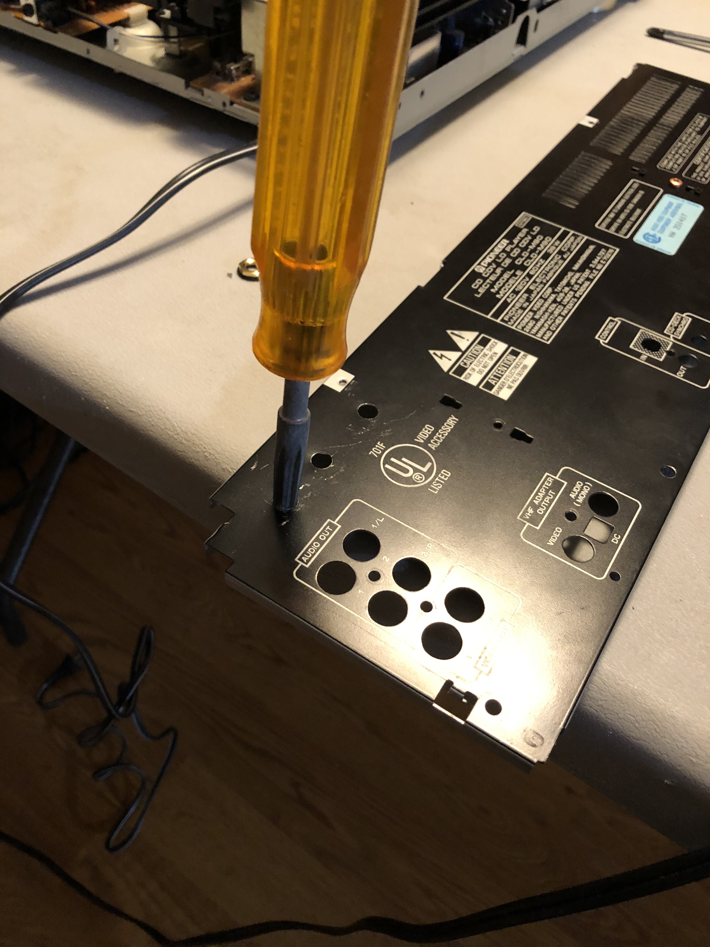
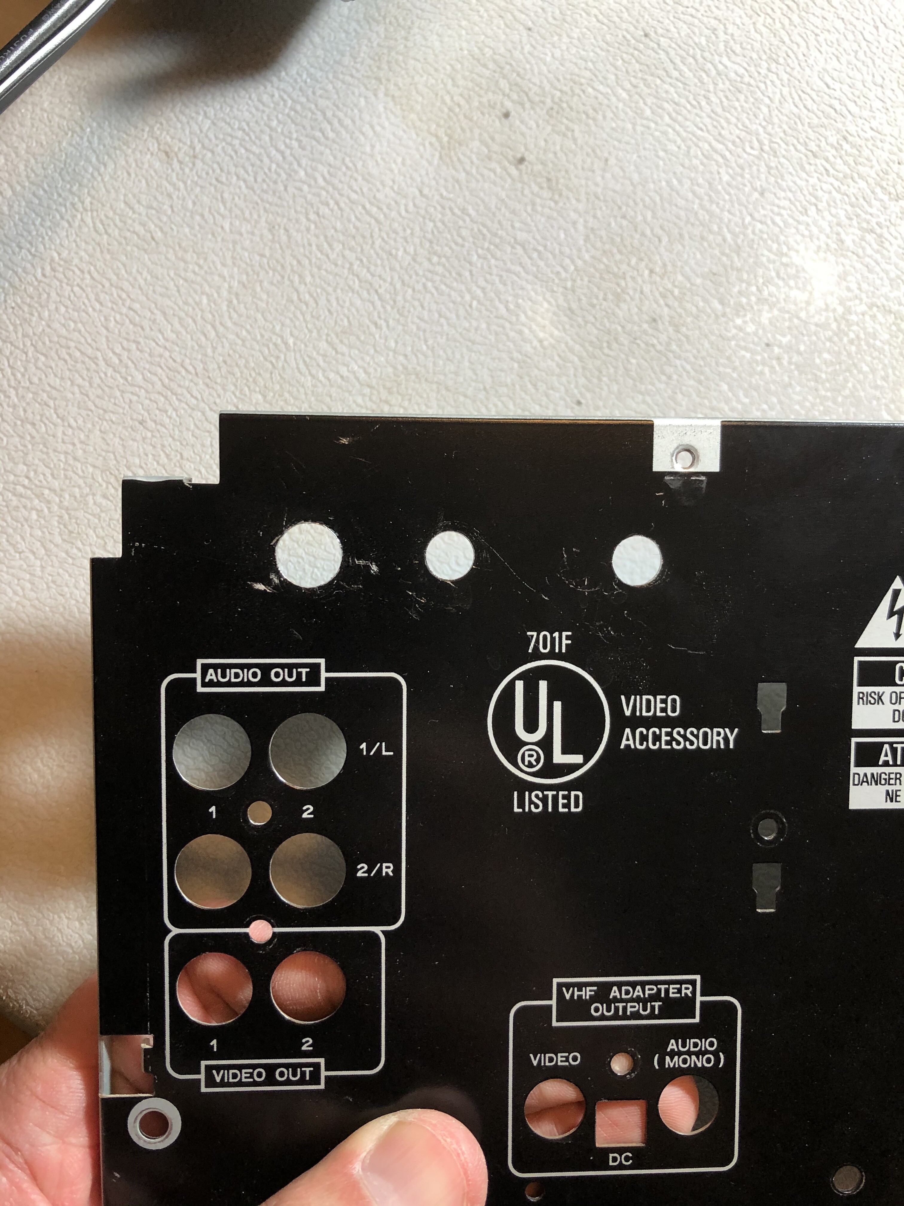
In any case, let's get to the back panel. Of course, one has to remove it off of the player for the sake of ease especially since I'm going to be punching out three holes instead of the usual one hole in my previous mods. The panel came off pretty easily with only nine screws holding it in place.
Now let's turn the panel around to see where I'm going to punch out of the holes.
Here are the lines I drew out on the back to figure out a good placement as well as to line-up all three holes evenly....
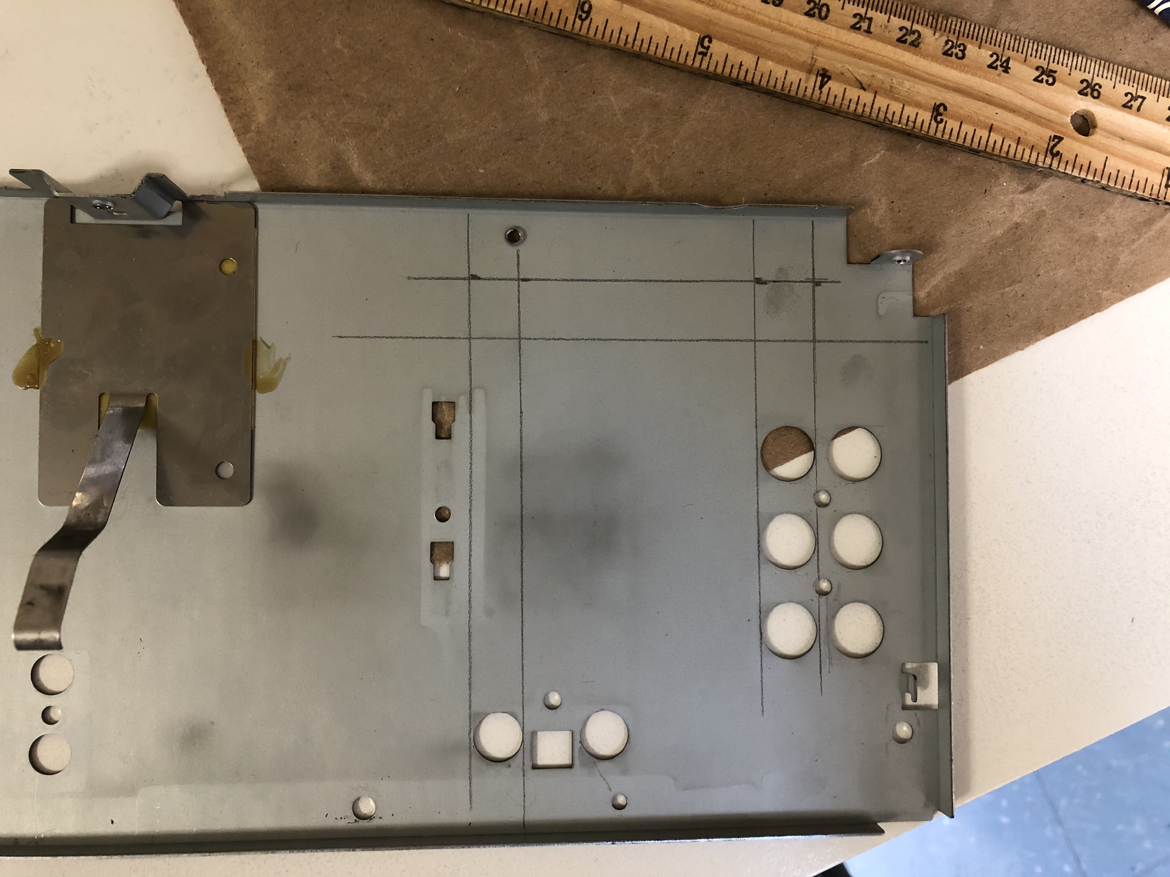
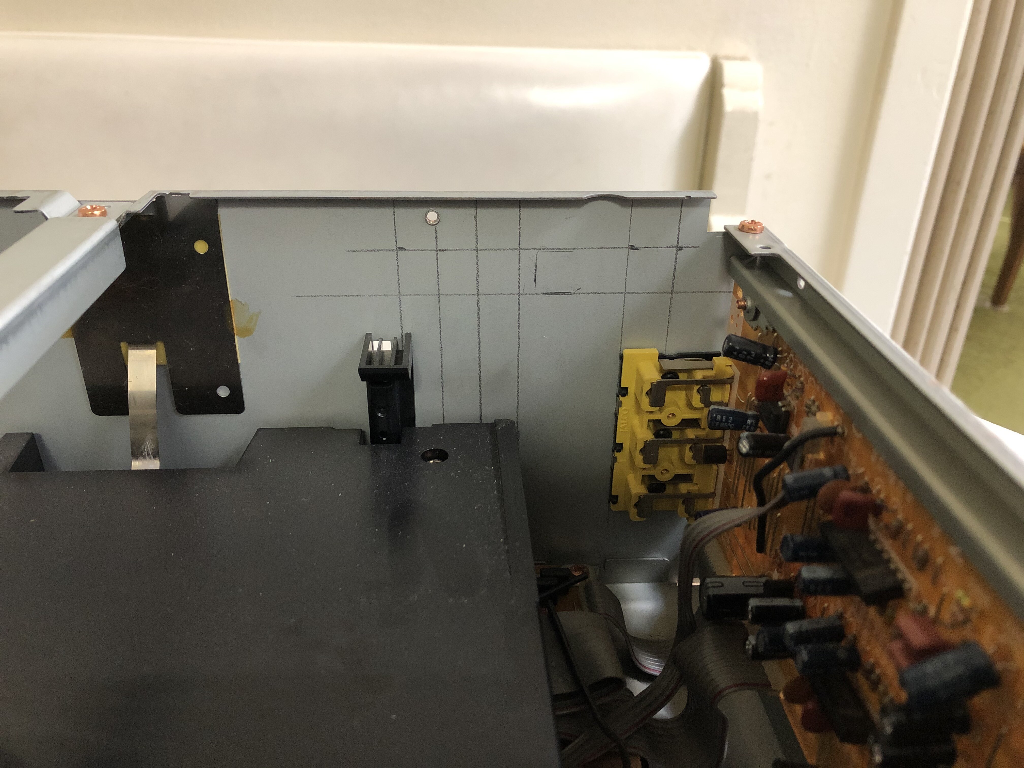
..... and finally a test fit to see if any obstructions could be a problem.
The next step is to just punch out the holes with my Roper Whitney #5 Junior Hand Punch using the 3/32" punch size (about a 1/4" diameter).
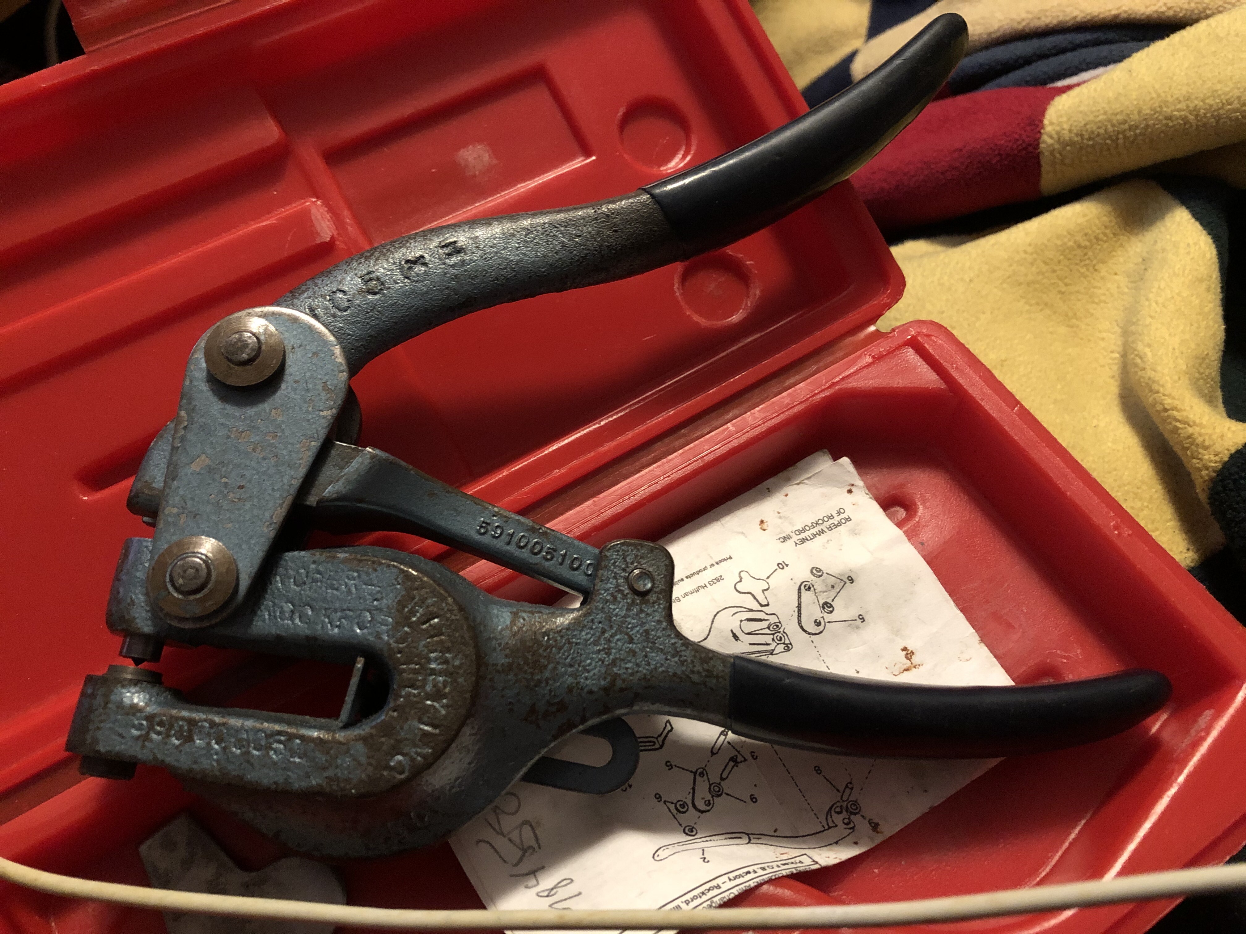
I prefer this over drilling as I feel it's a less risky option in respect to slipping or even bending the back panel if I was to apply pressure w/ a drill
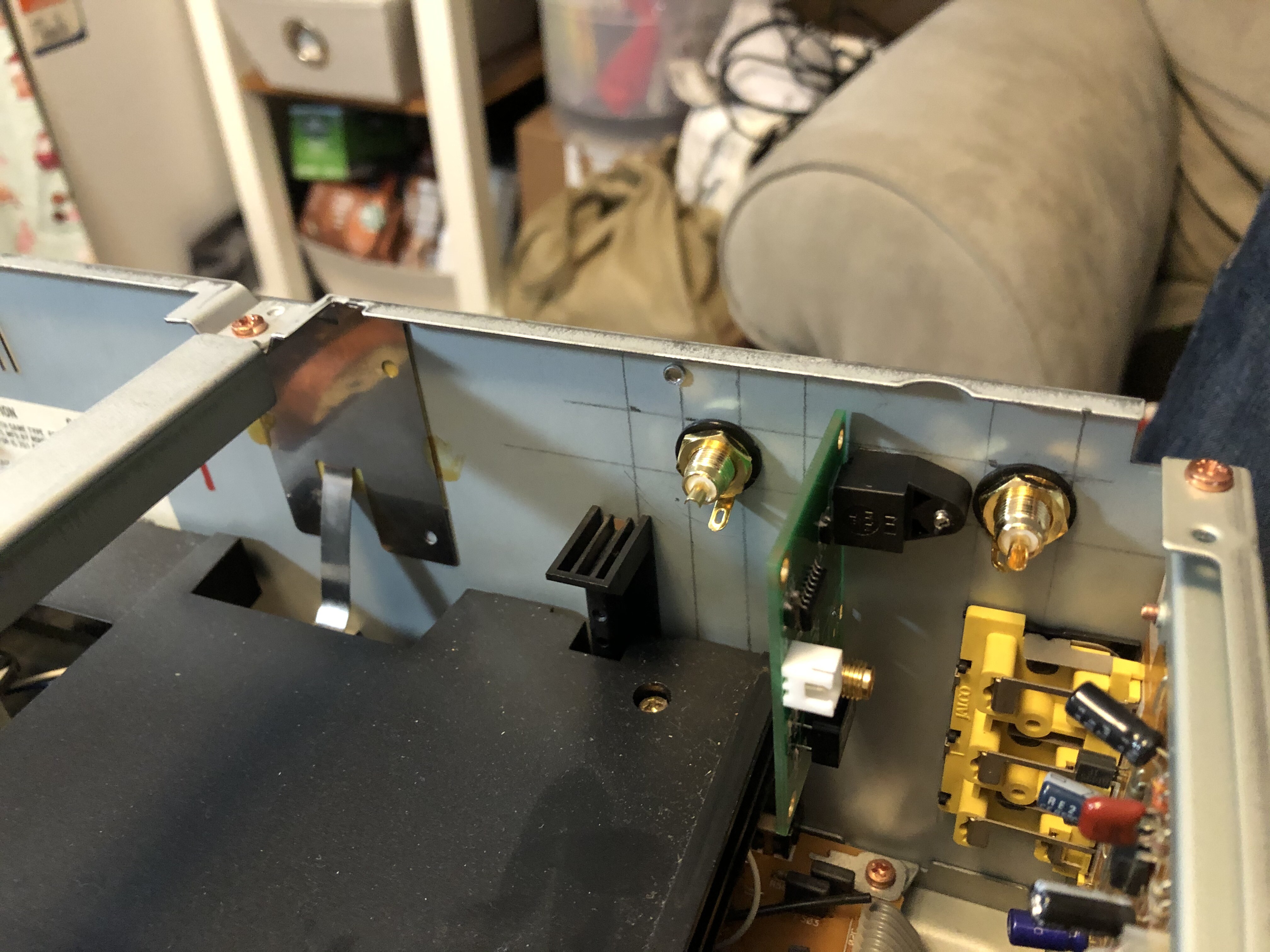
I chose the following locations based on trying to line-up them up w/ the other RCA jacks on the bottom (at least on the left side) but I especially wanted my new jack openings to be straight across the top.
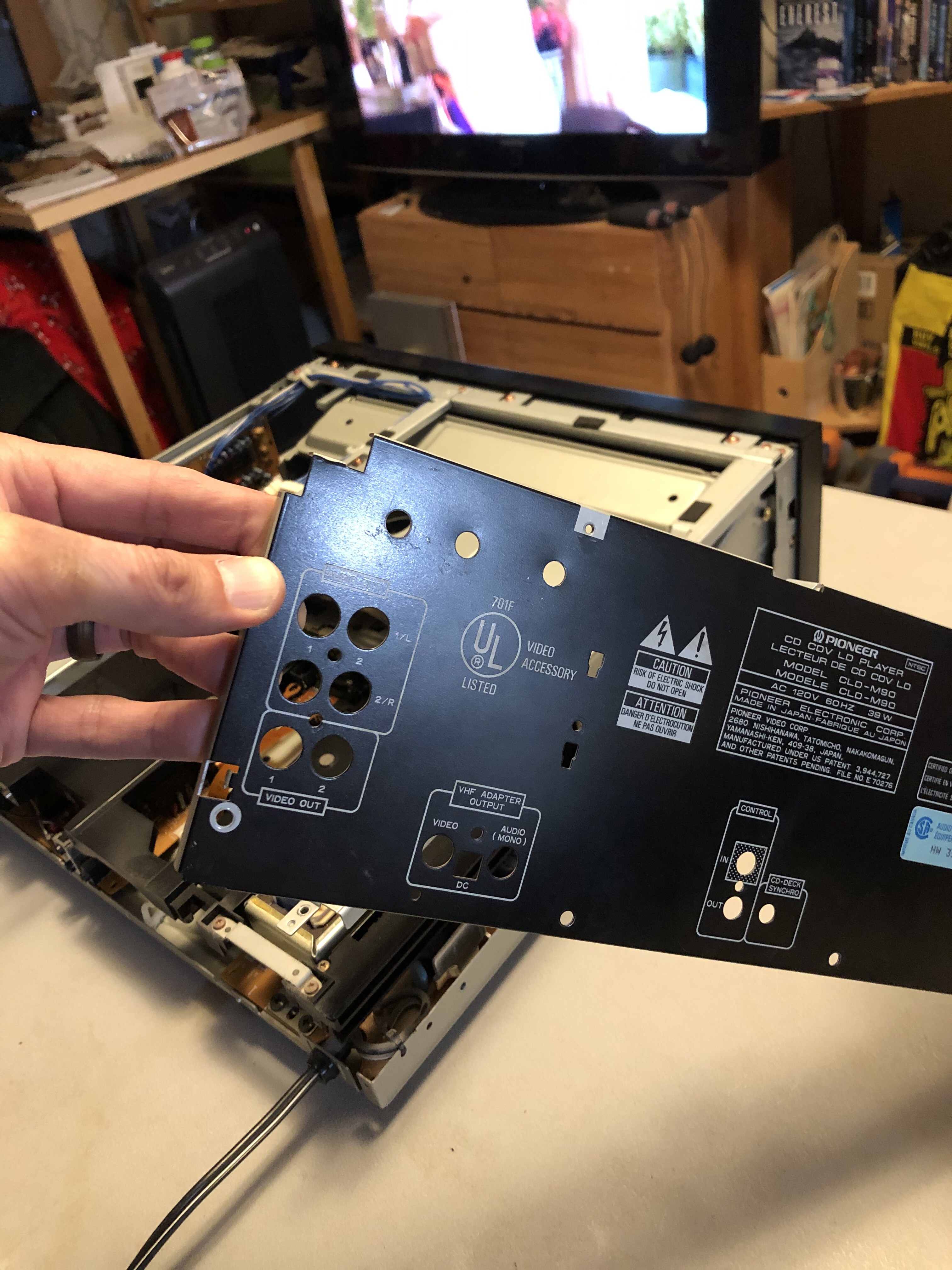
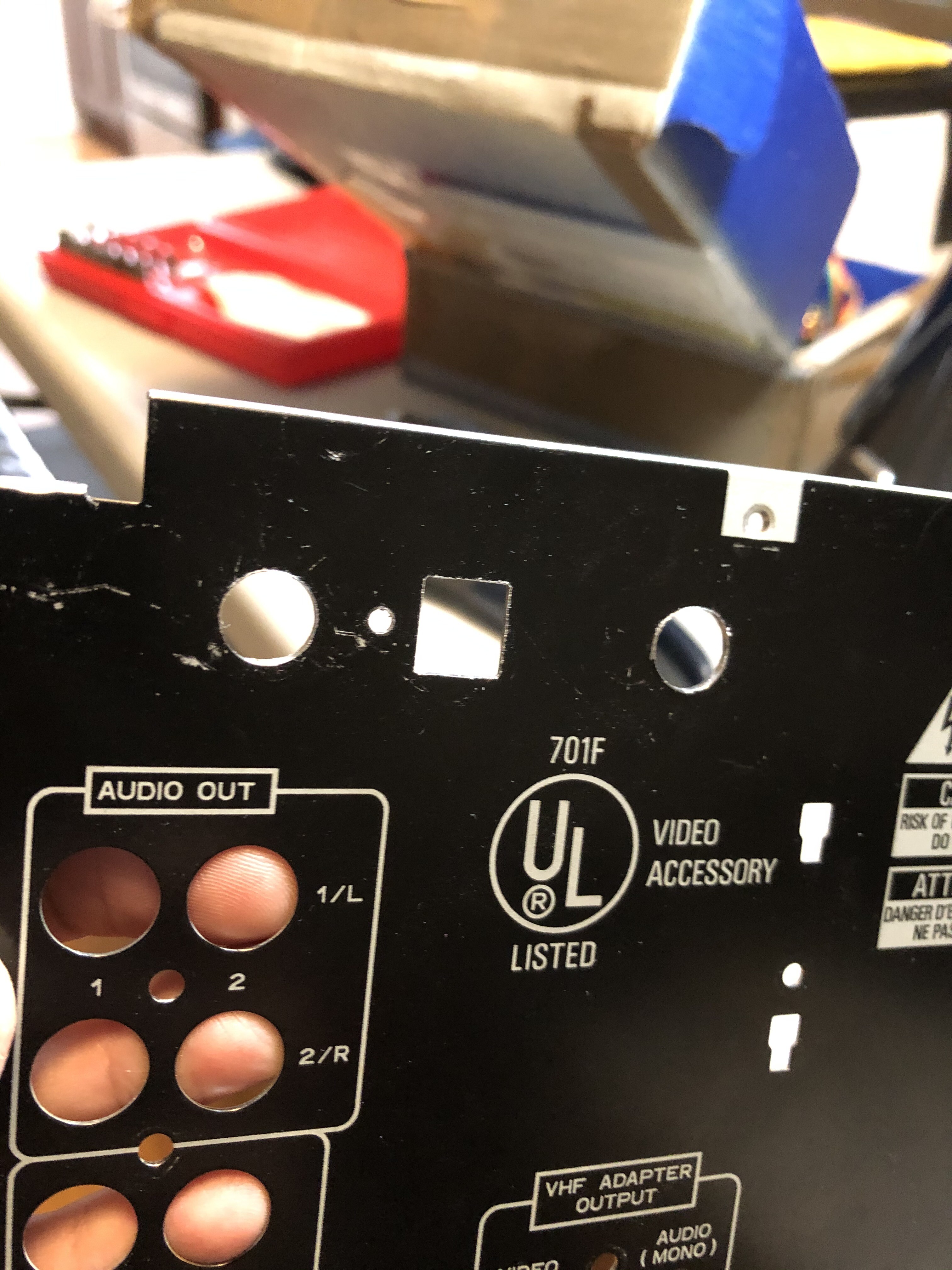
Next, I needed to enlarge all three holes w/ a reamer as they were all just a tad too small for the RCA jacks and the optical transmitter.
The hole on the left is now enlarged and still looks nice and clean.
So now the challenge is to make a square opening for the optical transmitter. I first start w/ getting a template of the exact size I need and I found it on a CLUX HDMI Extractor.
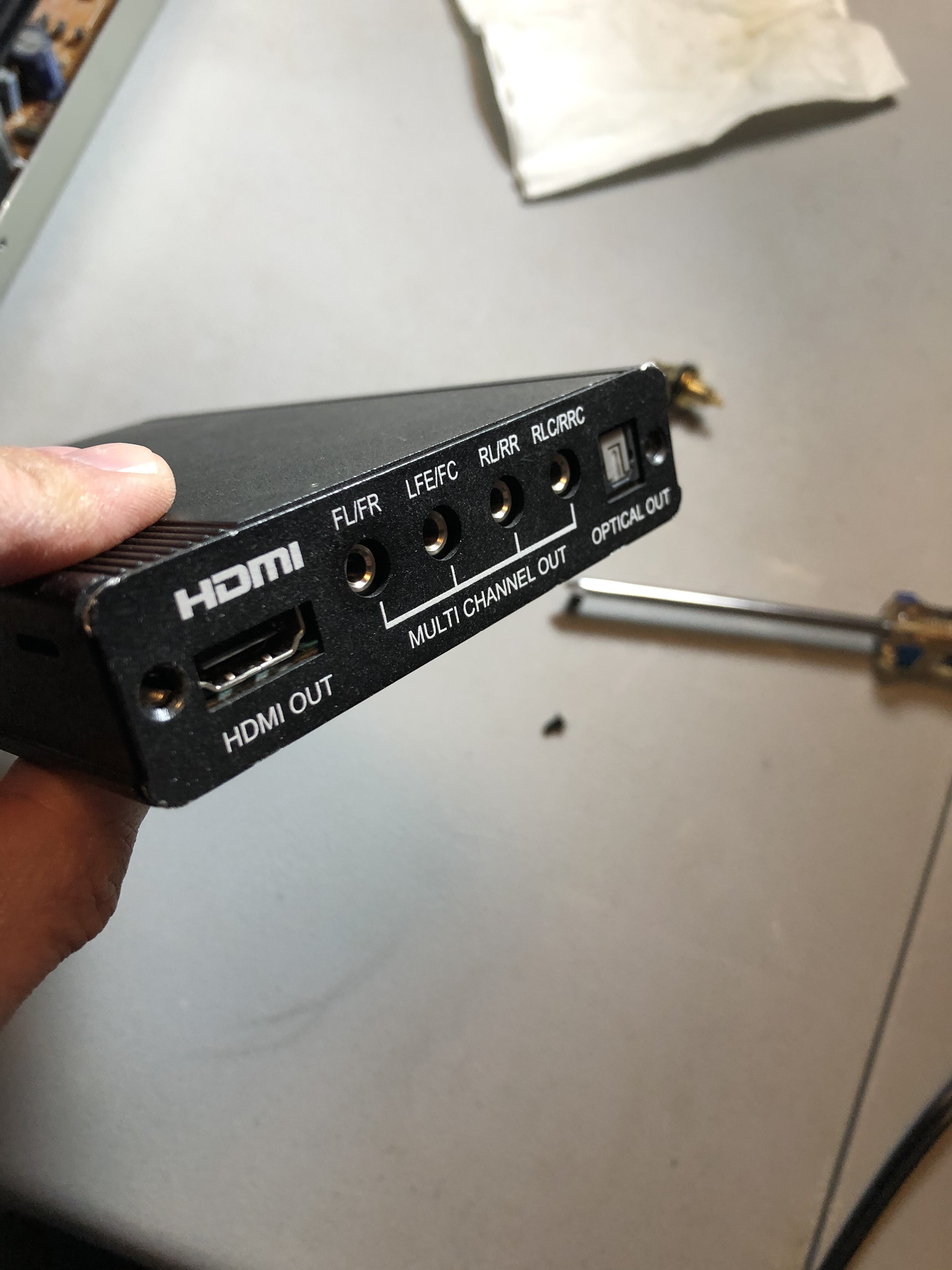
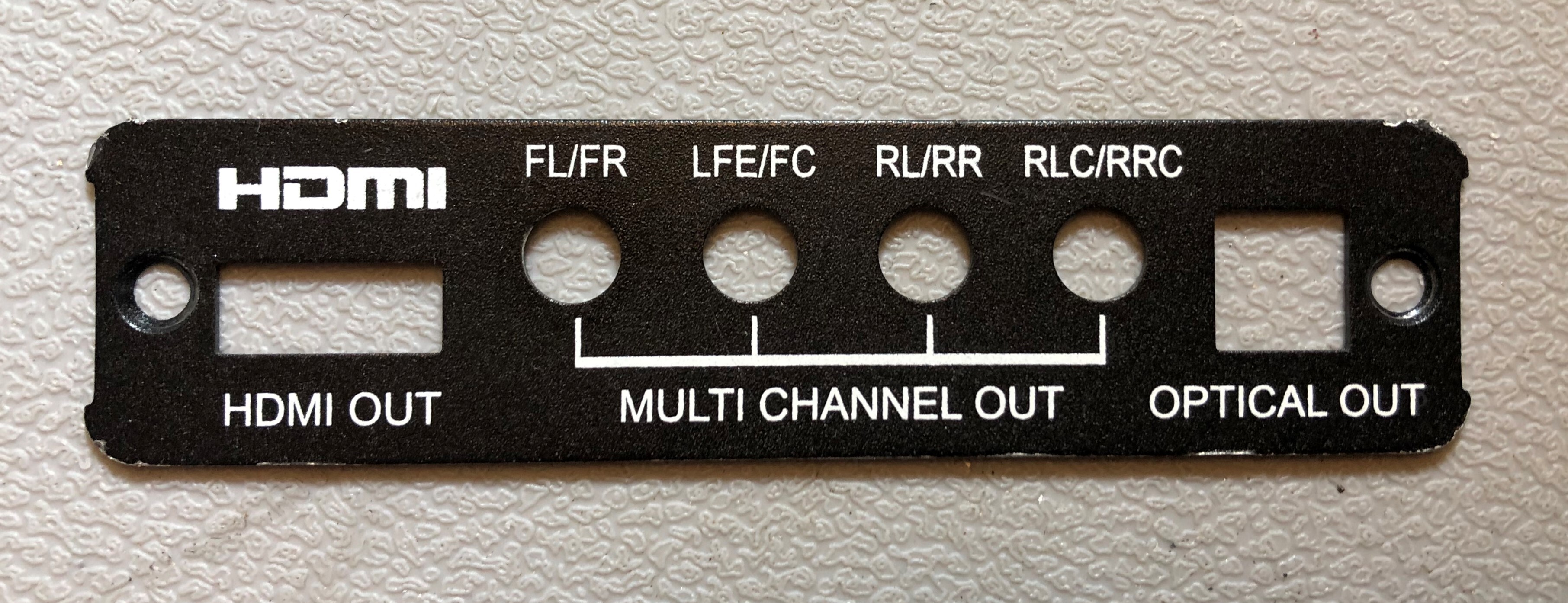
I had the CLUX faceplate removed and centered it on the hole I needed shaved out (and used double stick tape to secure it).
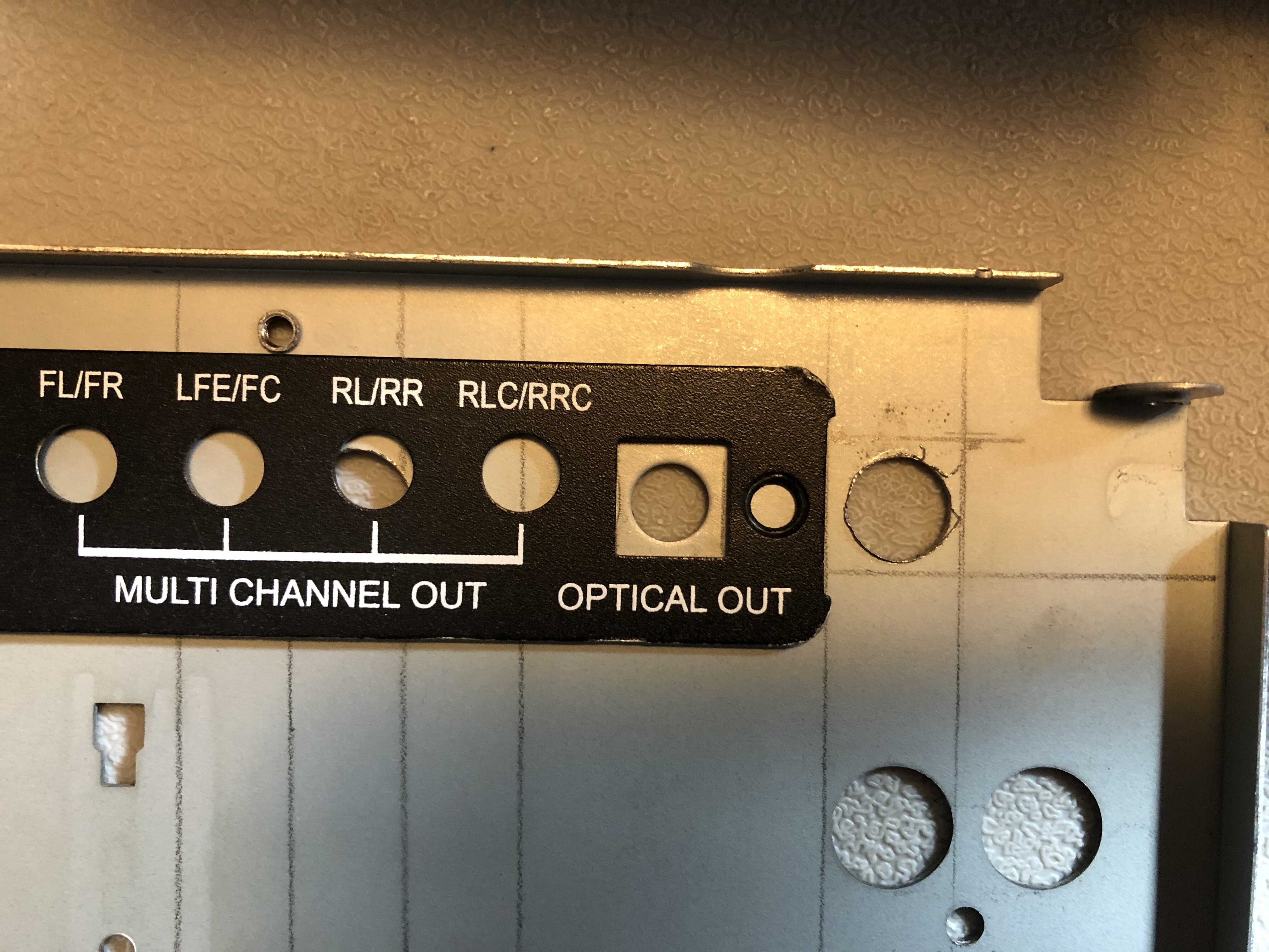
The next step is to use the reamer to enlarge the hole.....
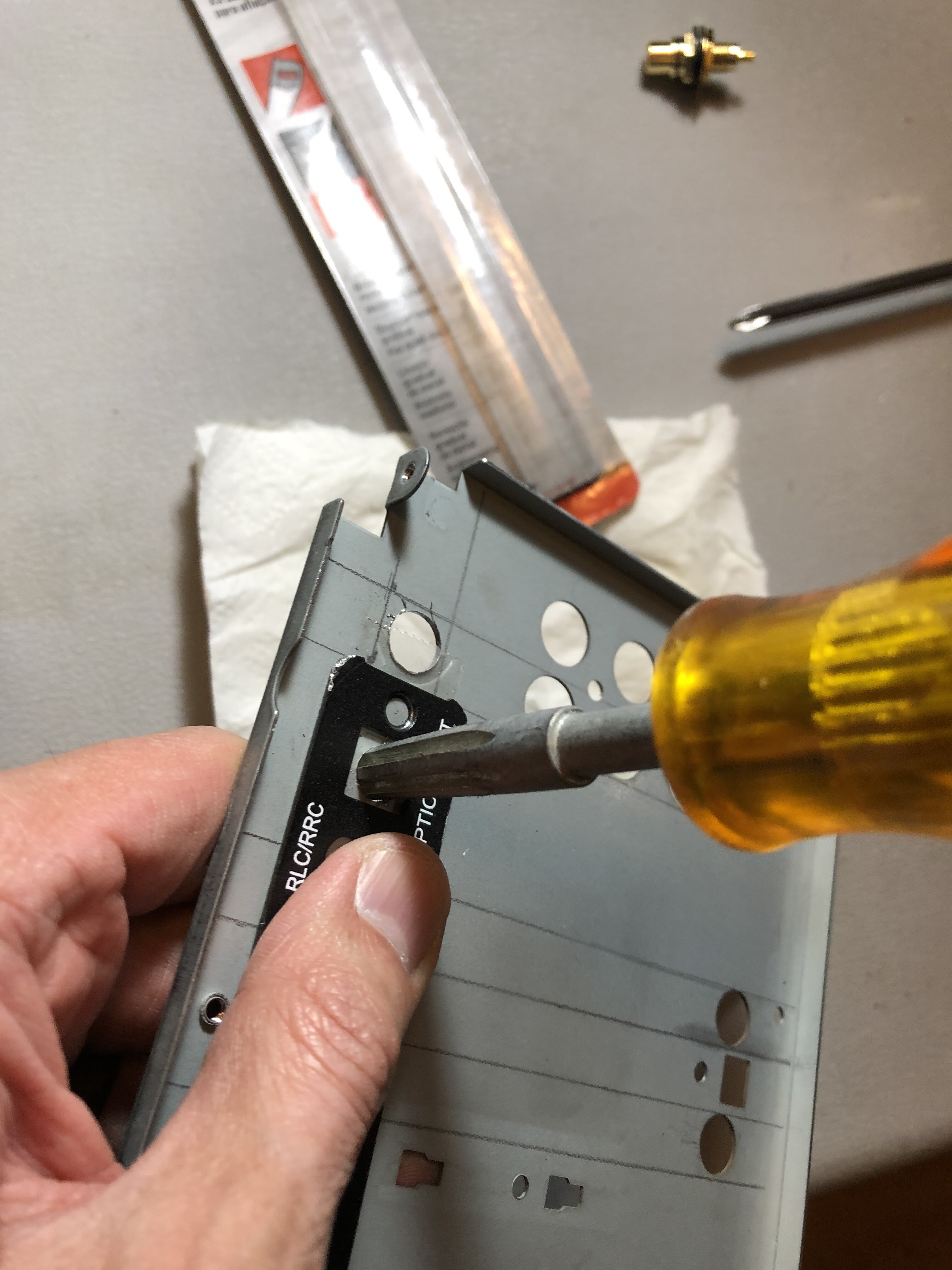

.....and then I'll switch to a triangular file (Crescent Nicholson 21874NN)
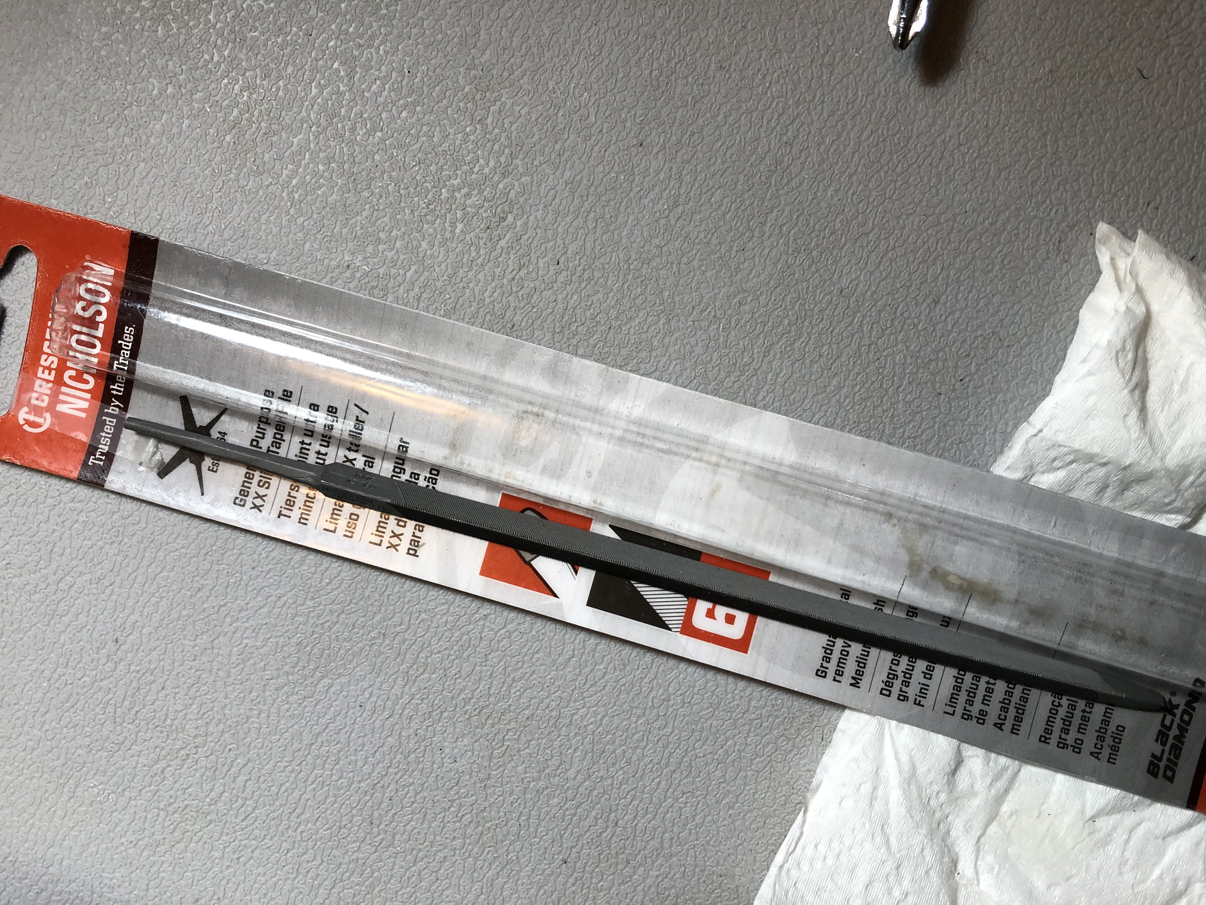
(thanks to "integra" for the advice on the file he used on his ADP-303 mod

).
This took awhile to grind down but the results were amazing.
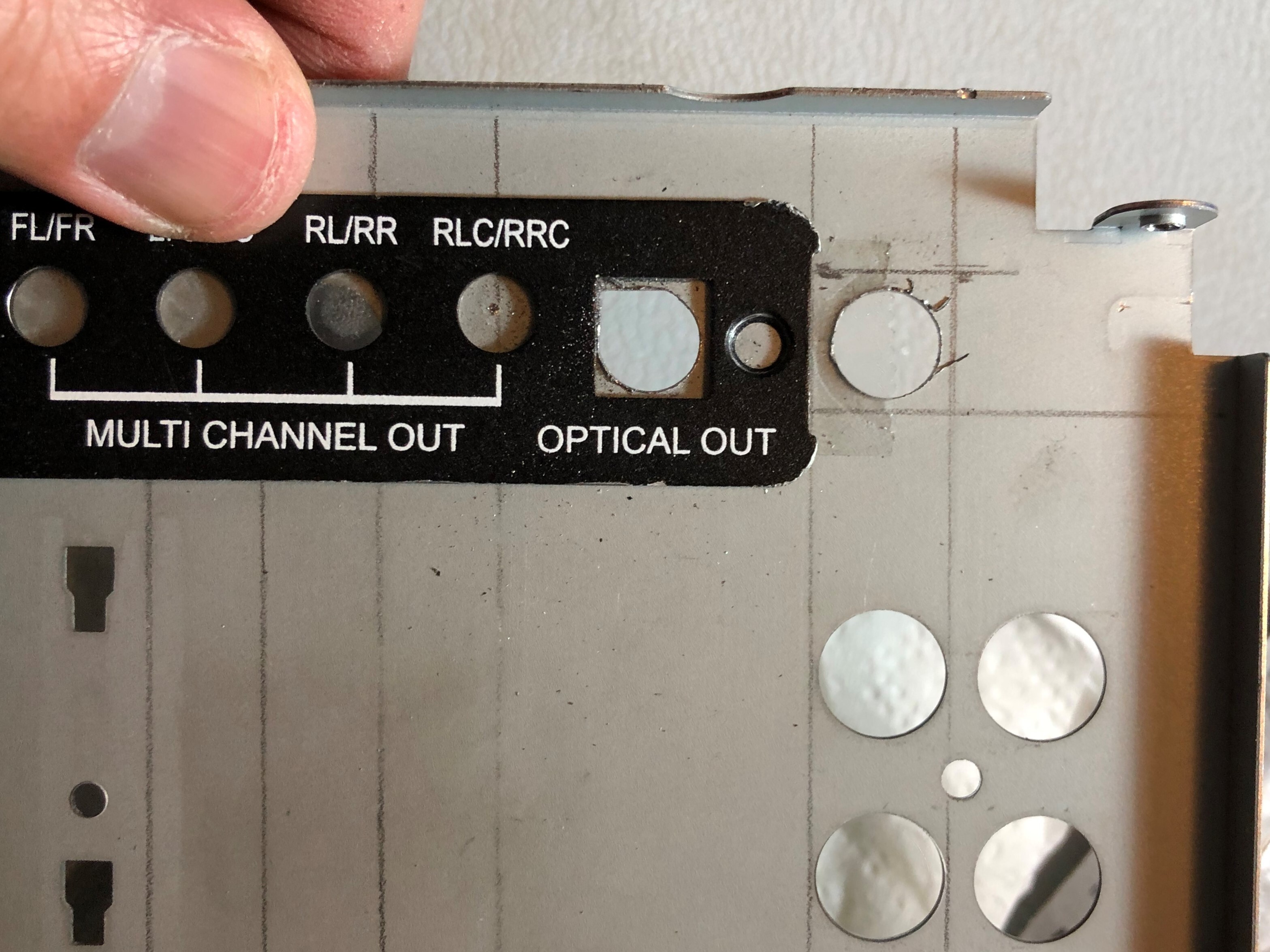

Here is the optical transmitter being test fitted and it's a perfect fit.....
..... and now showing a screw hole punched out to mount the optical transmitter
Now we have all three jacks mounted.....
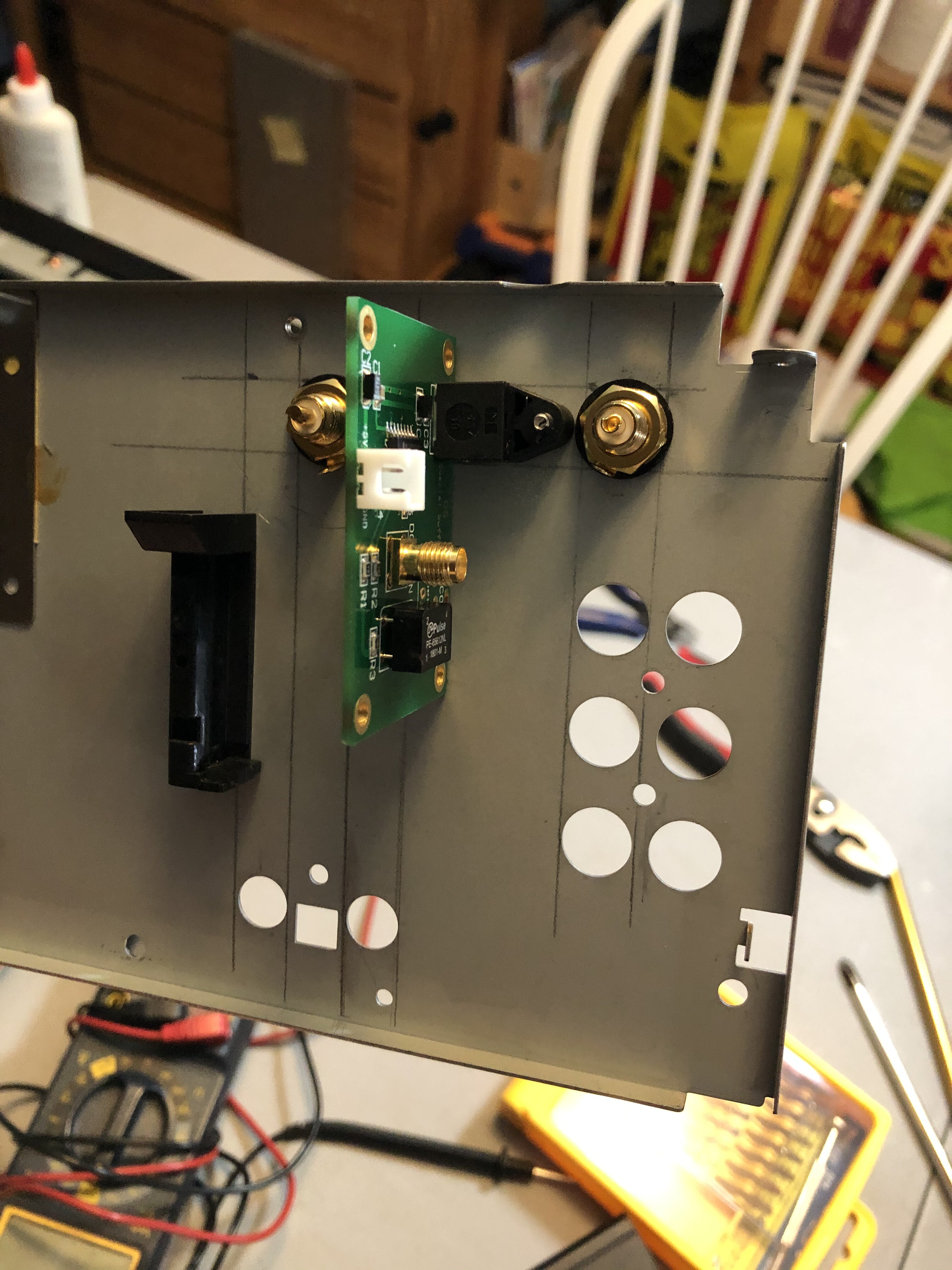
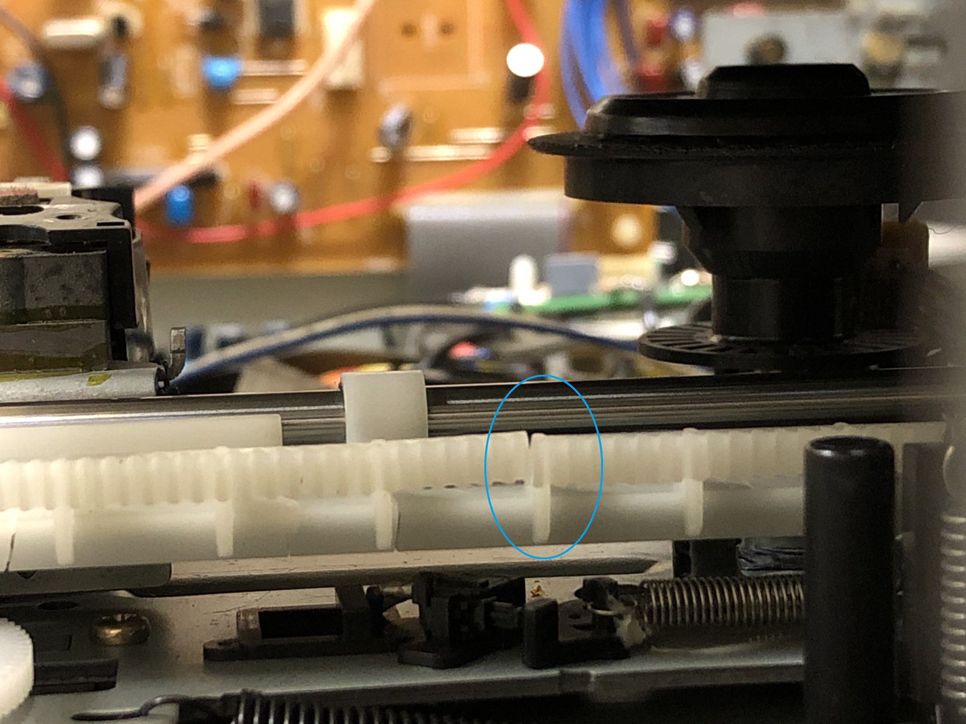
.....and tested for clearance w/ the tray retracted.
Now it's time to move on to the next segment of this mod (but I'll still cover more about these jacks toward the end).
Digital Output ModMy first step was to first remove the optical transmitter that came w/ the board as the original transmitter came with no mounting hole (the intent of this board was to use the board itself as the basis of a mount but that wasn't going to work here). Also, I had the RCA jack removed as I did not like the way it extended out and I wanted it to match the other RCA jack for the AC3-RF Out.
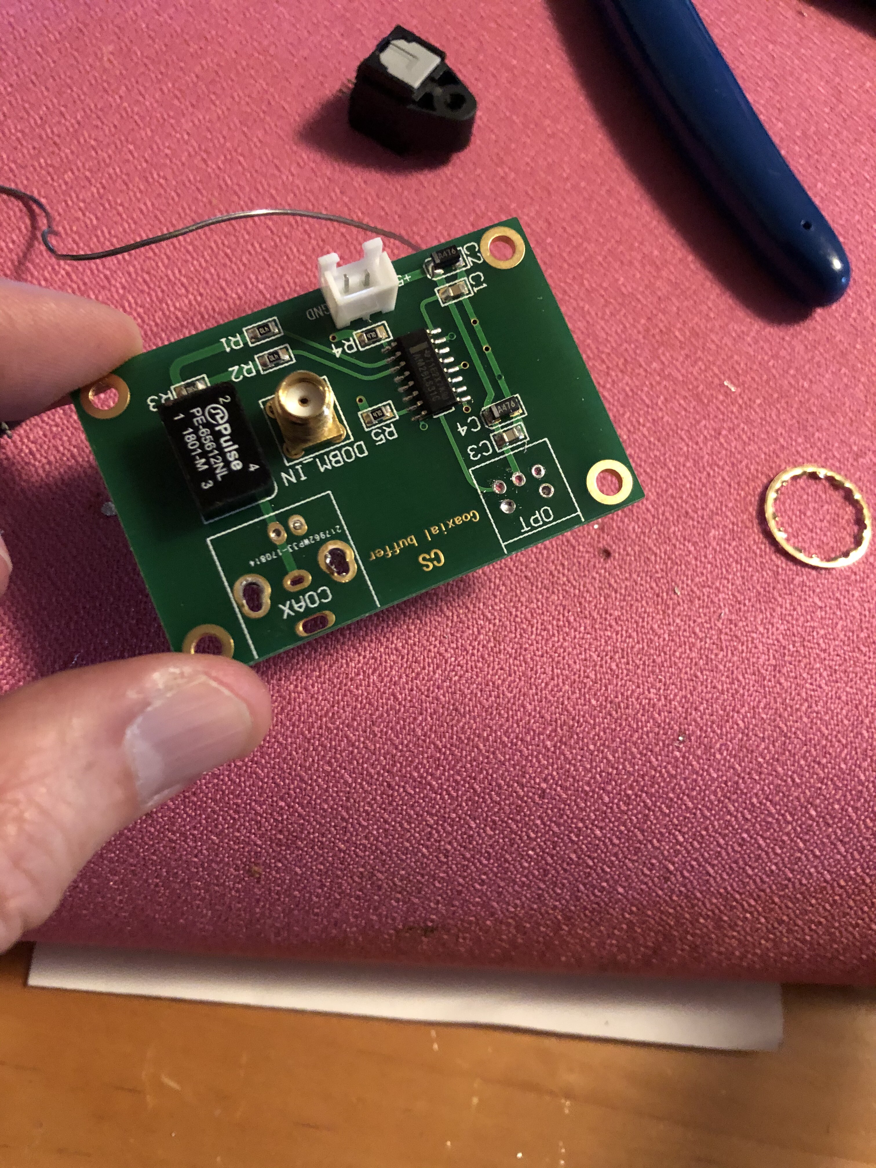
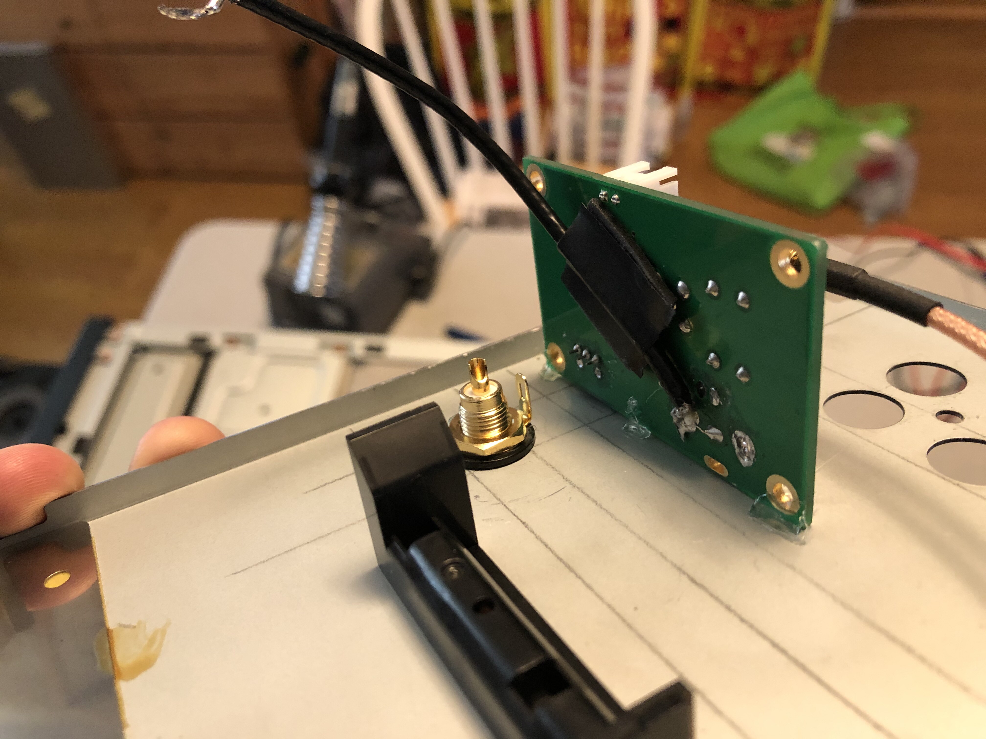
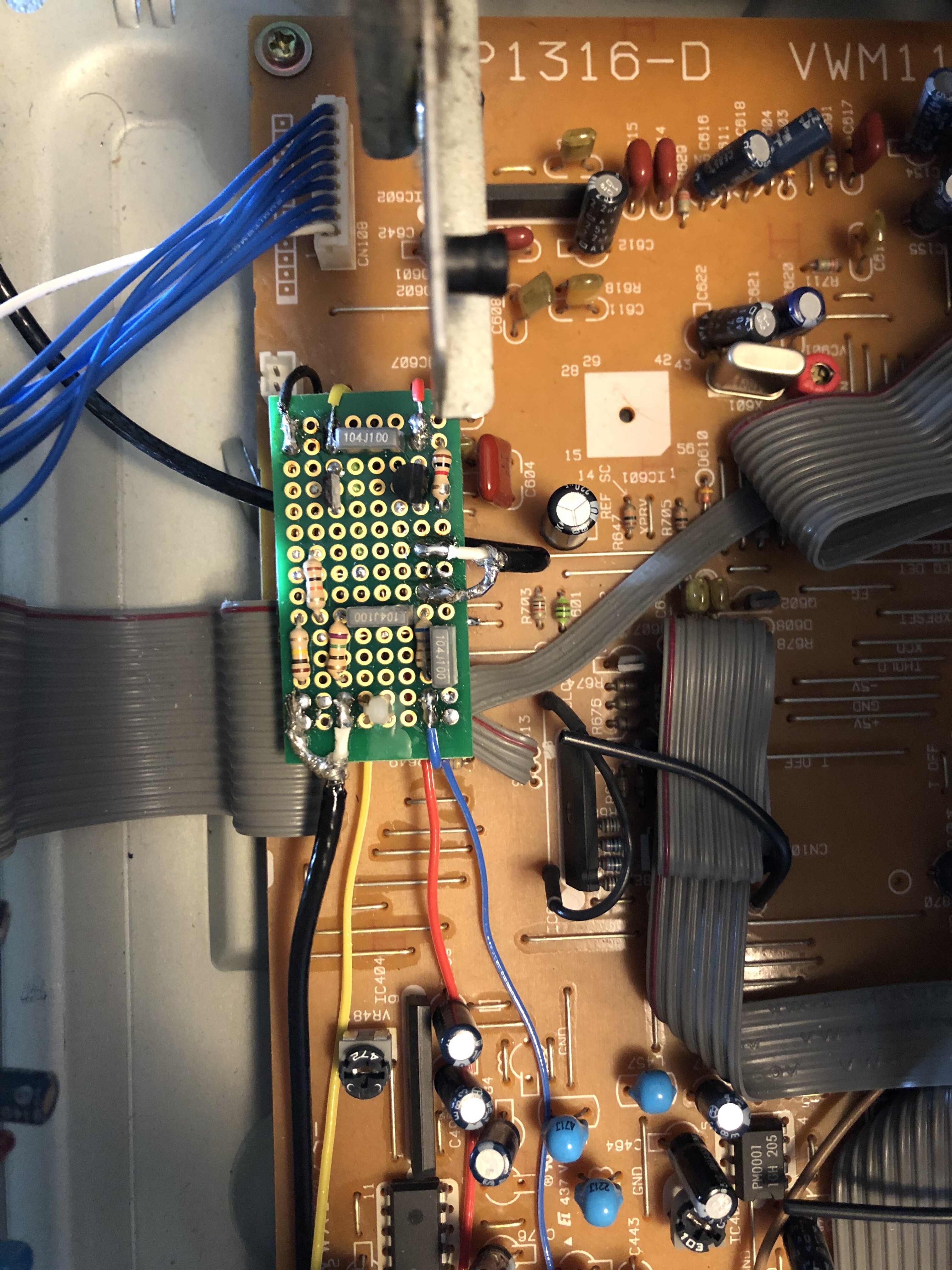
Here is the board now w/ the new optical transmitter now soldered in and I also had hot glue added to the sides to strengthen its connection to the board (the transmitter housing is not well secured to the transmitter itself so the glue was necessary).

Moving on, I soldered in a coax wire to the pad where the RCA jack used to reside so I could connect it up to the new jack I have mounted to the back panel.
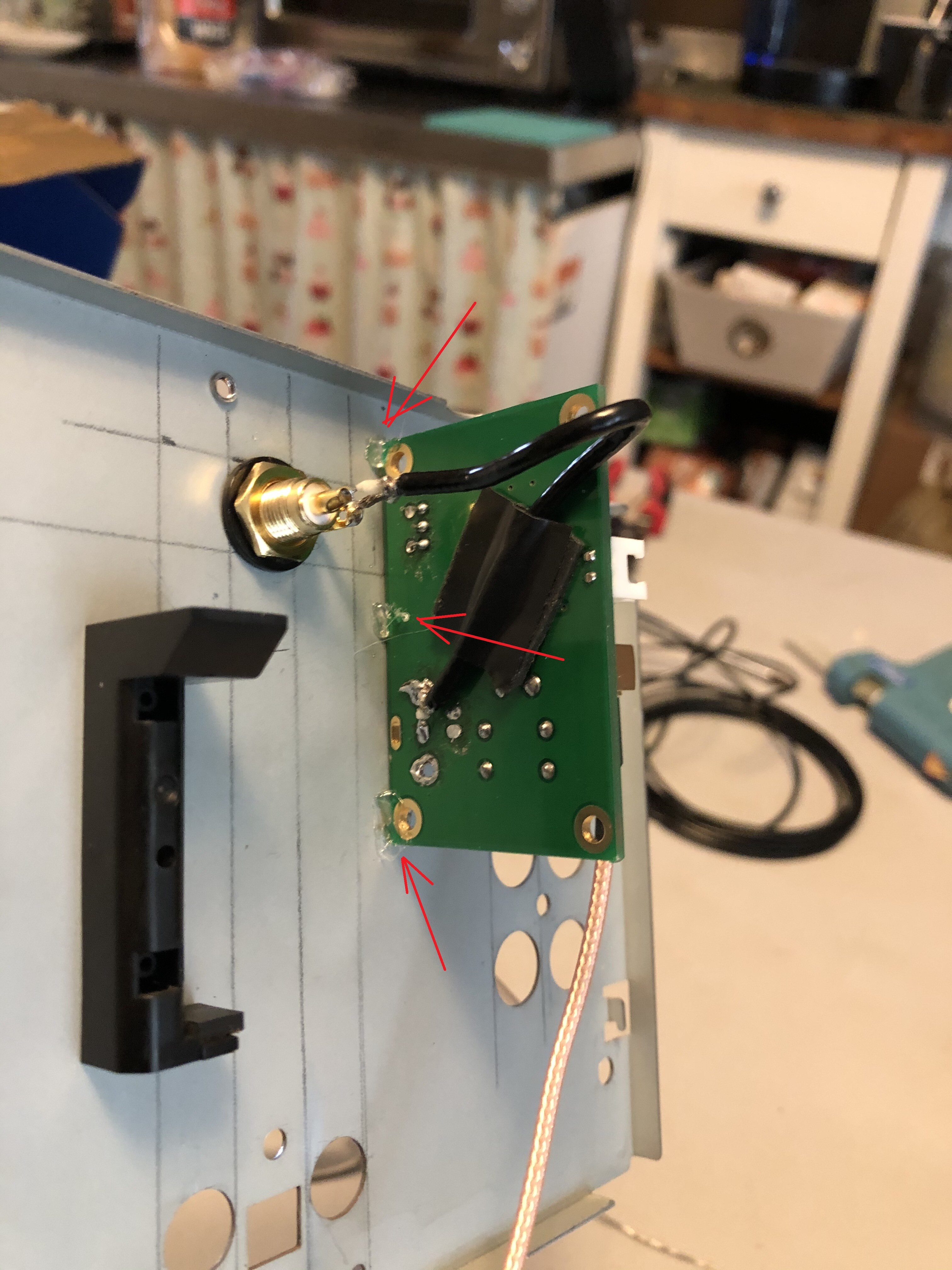
(red arrows indicate hot glue to add additional mounting strength for the board to the back panel)
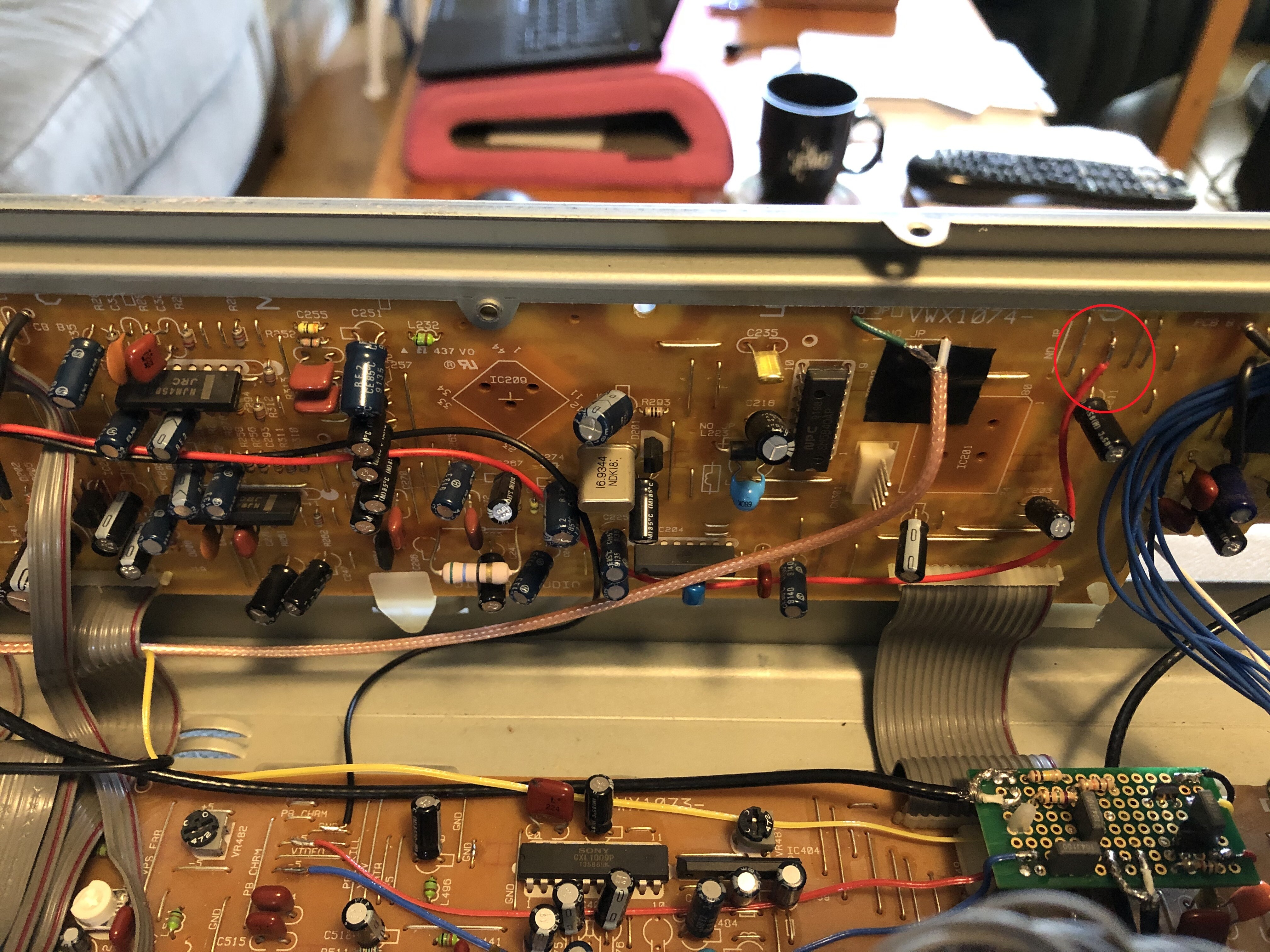
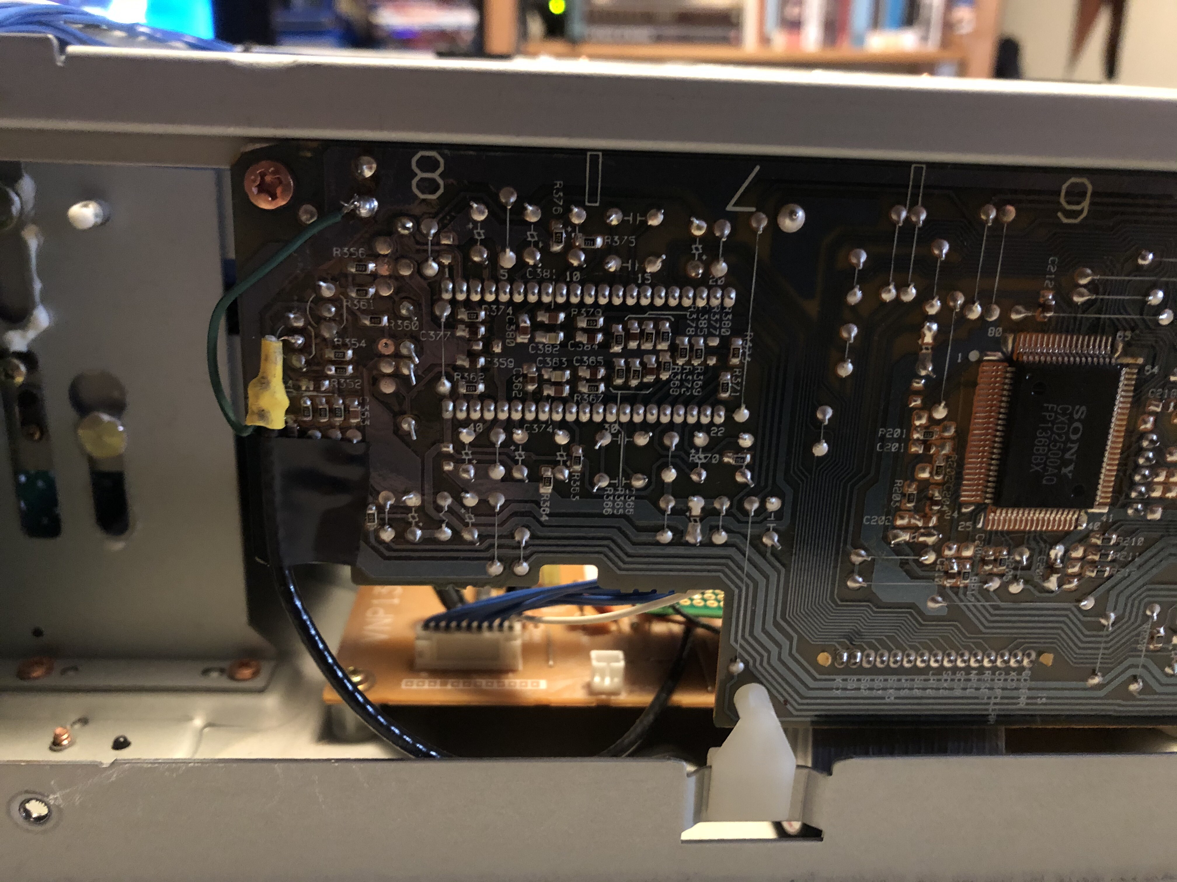
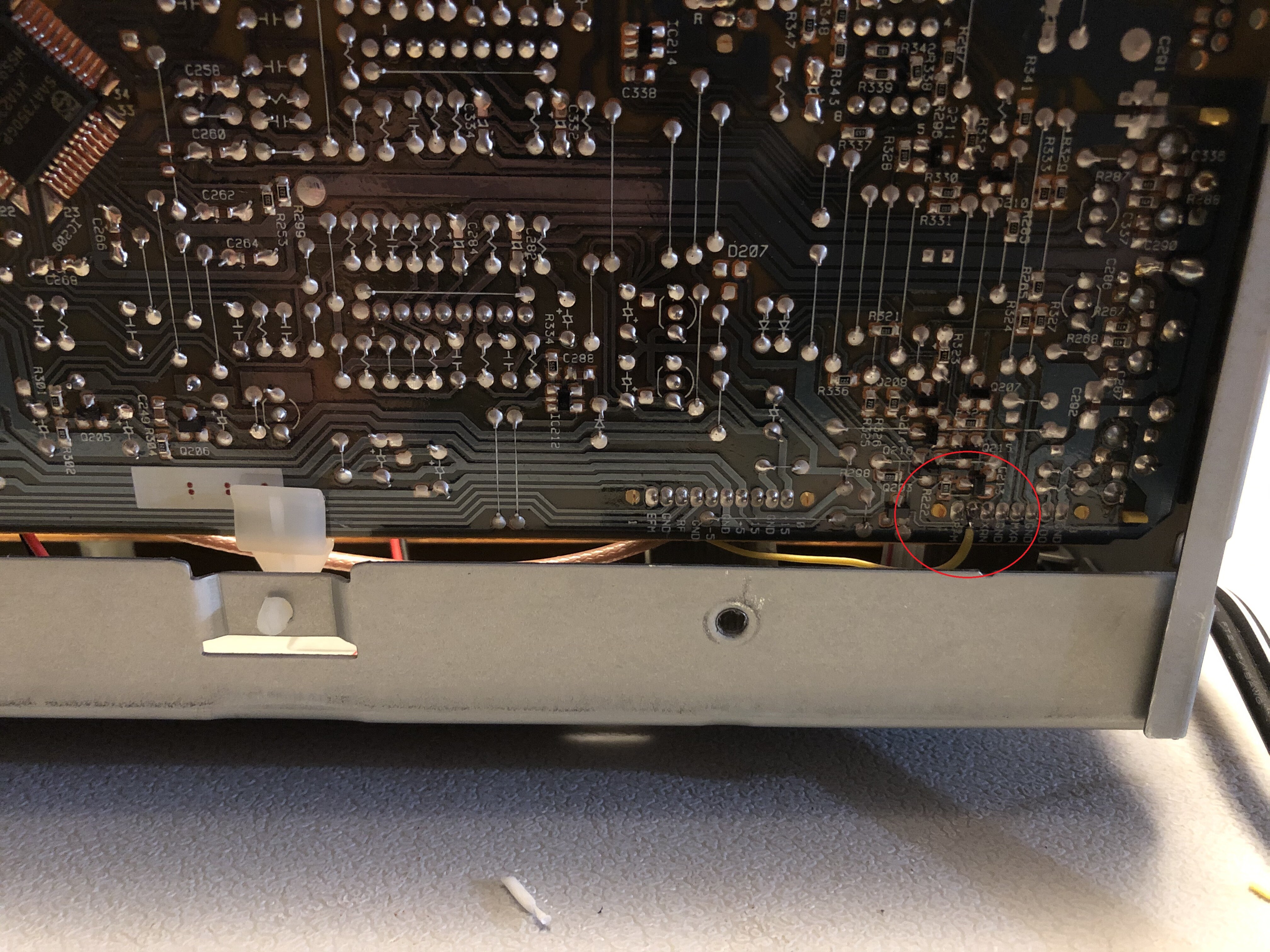
Now it's time to tap the digital signal from the player to the board. The interface is right off the Sony CXD2500AQ DSP as shown here.
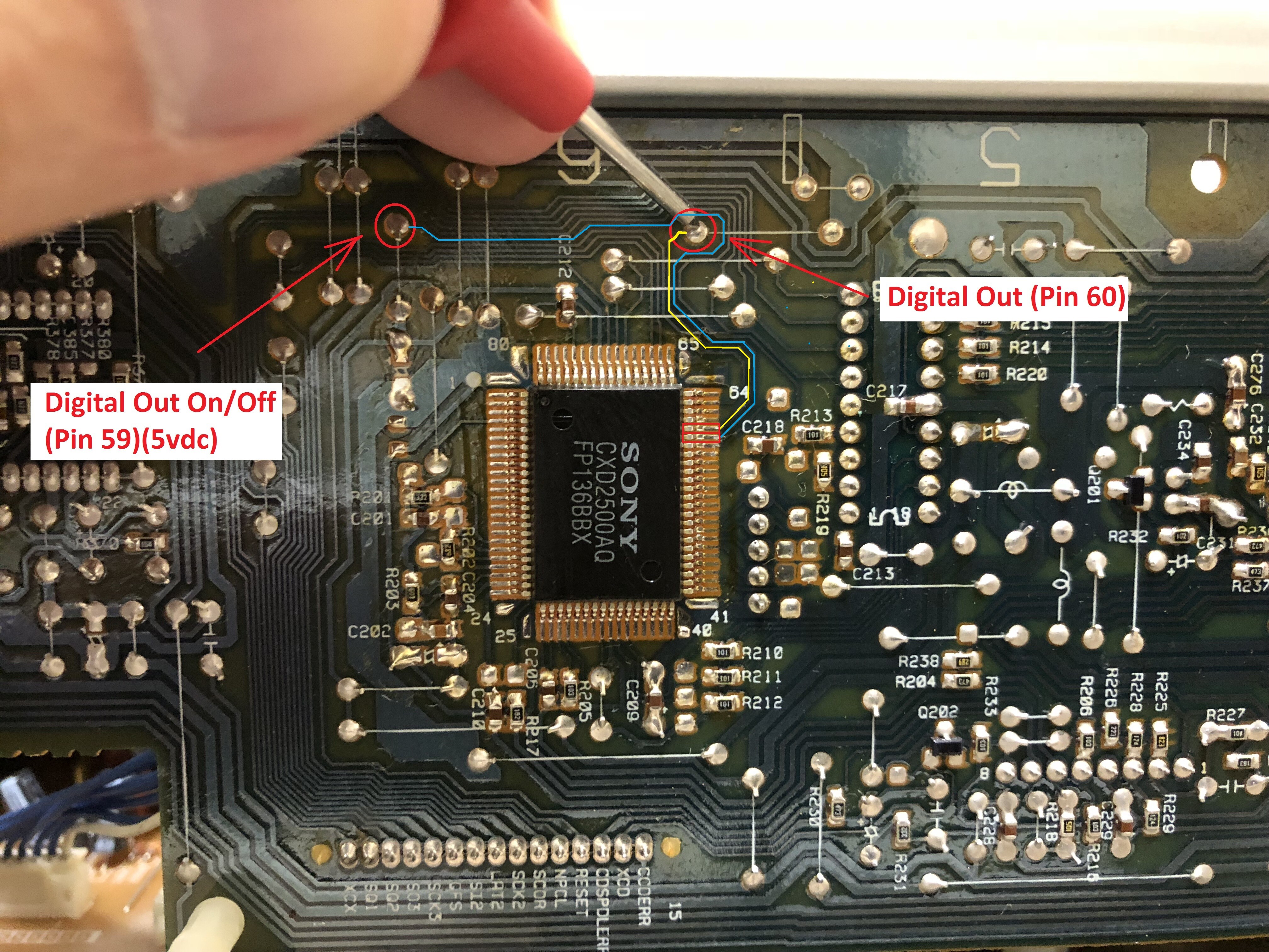
Pin 60 will be the tap to provide the signal while Pin 59 is just a verification that the digital output is set to "on" (if there was 0 vdc on pin 59, I would have to jumper a 5vdc point to it). Fortunately, it was getting 5vdc so I didn't have to make any changes. The kit included a coax wire that was pre-tinned and I had it soldered in from the opposite side.
(coax wire to pin 60 and green wire to GND)
Moving on, we'll also need a 5vdc power supply so that was as simple as finding some jumpers that were already labeled.
The Digital Output is now complete and now it’s time to move on to the next step.
AC-3 RF Output ModSo I'll be using my 2nd scratch built AC3 board that I built over two years ago (can't believe it's been that long).
Top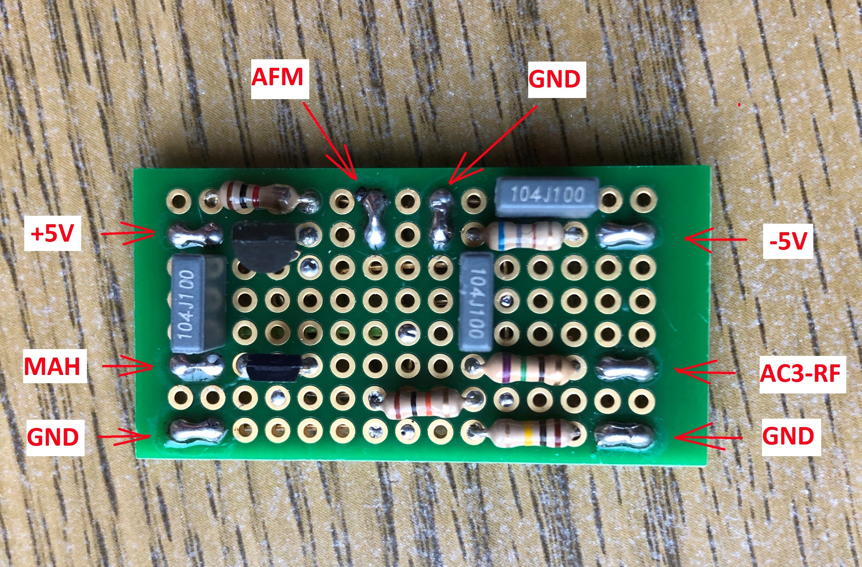 Bottom
I won't get into details regarding the board itself since I covered it in this previous post. >>>
Scratch built AC3-RF board installed in my ProScan, PSLD43 The focus here is mounting the board and running the wires.
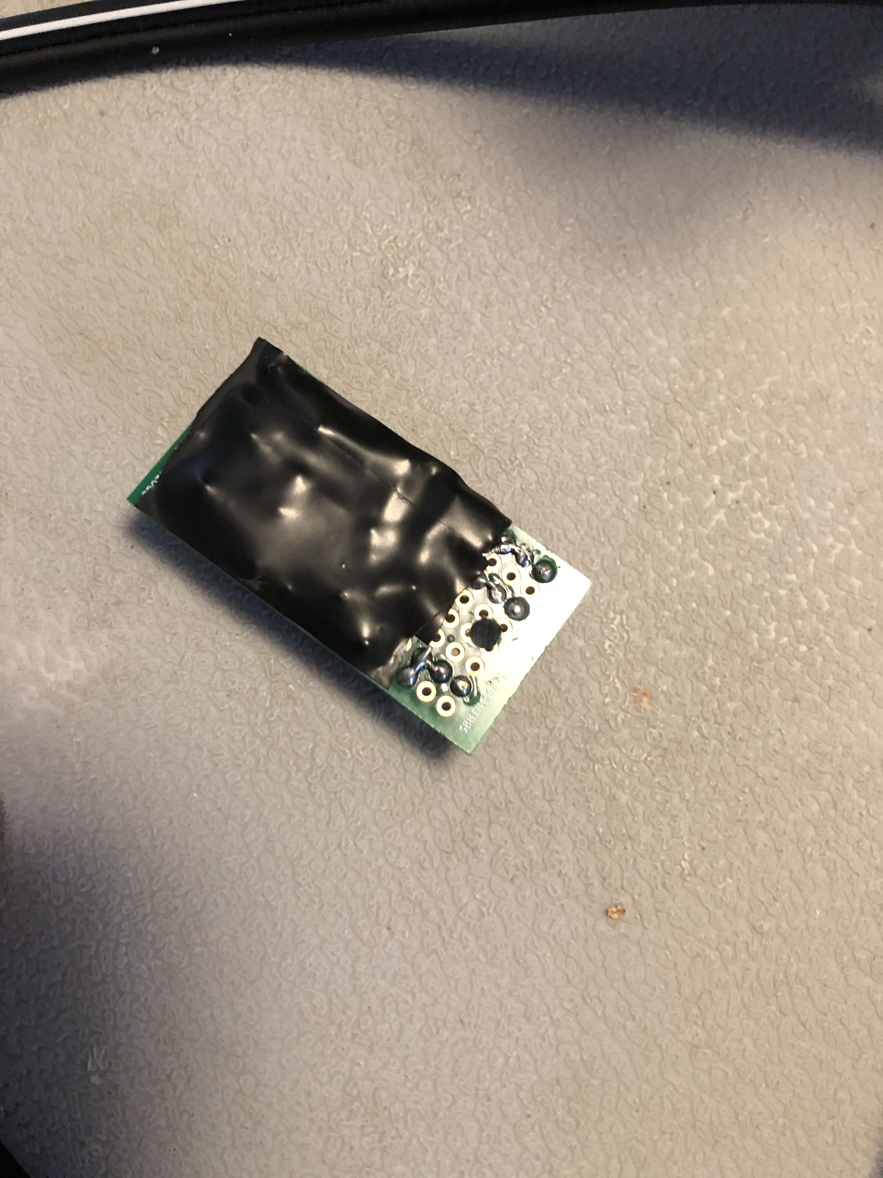
First step, I needed to punch a hole into the board so I can install a plastic stand off....
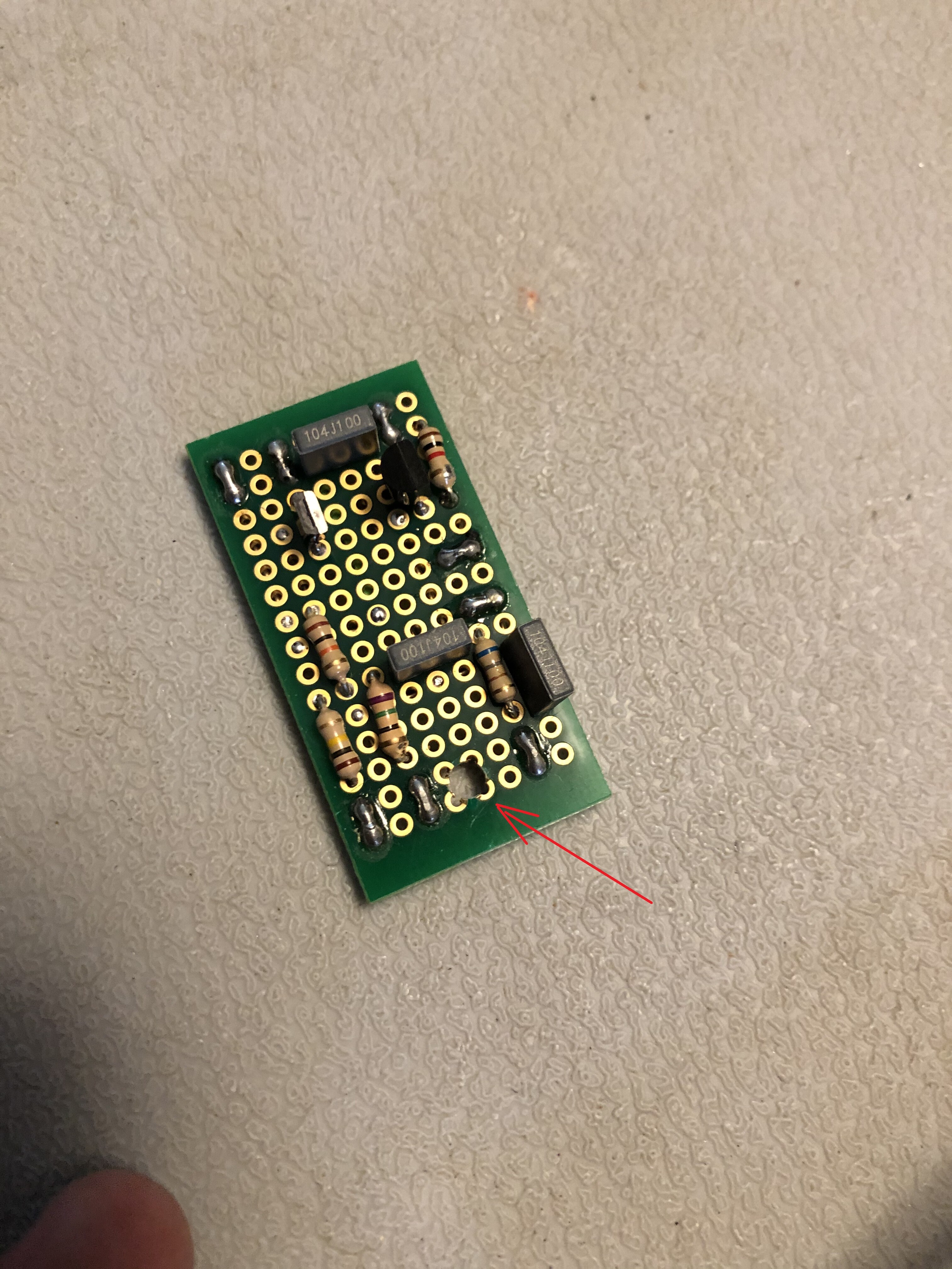
.... and put some electrical tape on the bottom of the board as a precaution against shorting in case it falls on to the main board.
Next up, time to pick a place to mount the board and I chose a location toward the front of the player that limits the length the AFM signal needs to travel to it (it was mentioned in instructions I have received in the past to keep this cable under 10" as a means to reduce signal loss but I'm not sure how definitive that advice is).
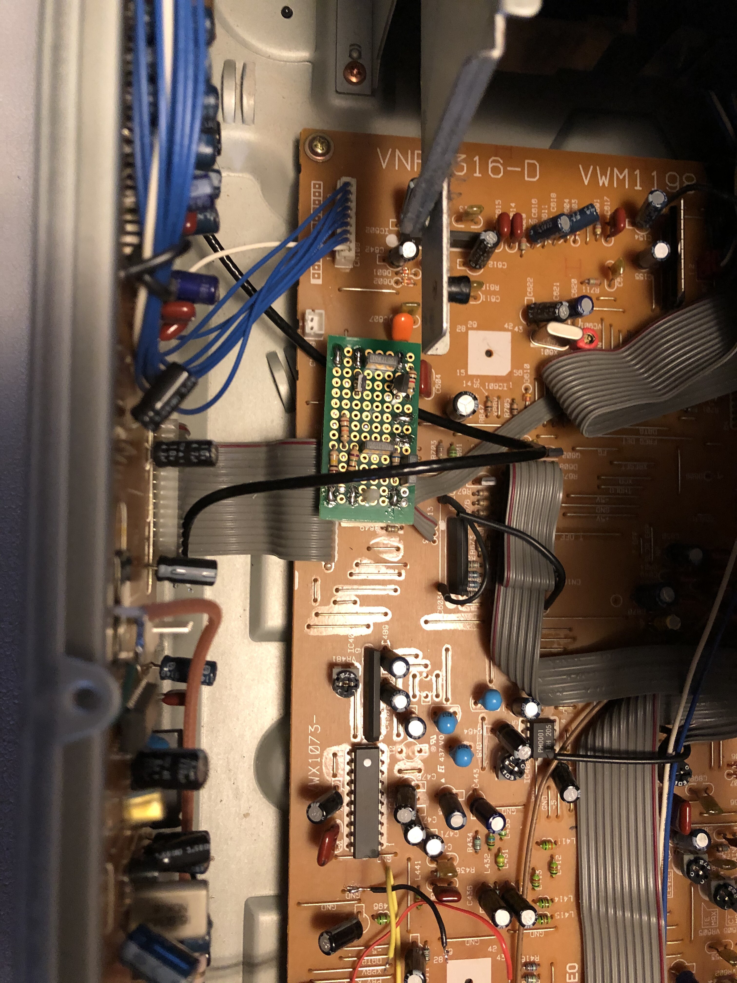
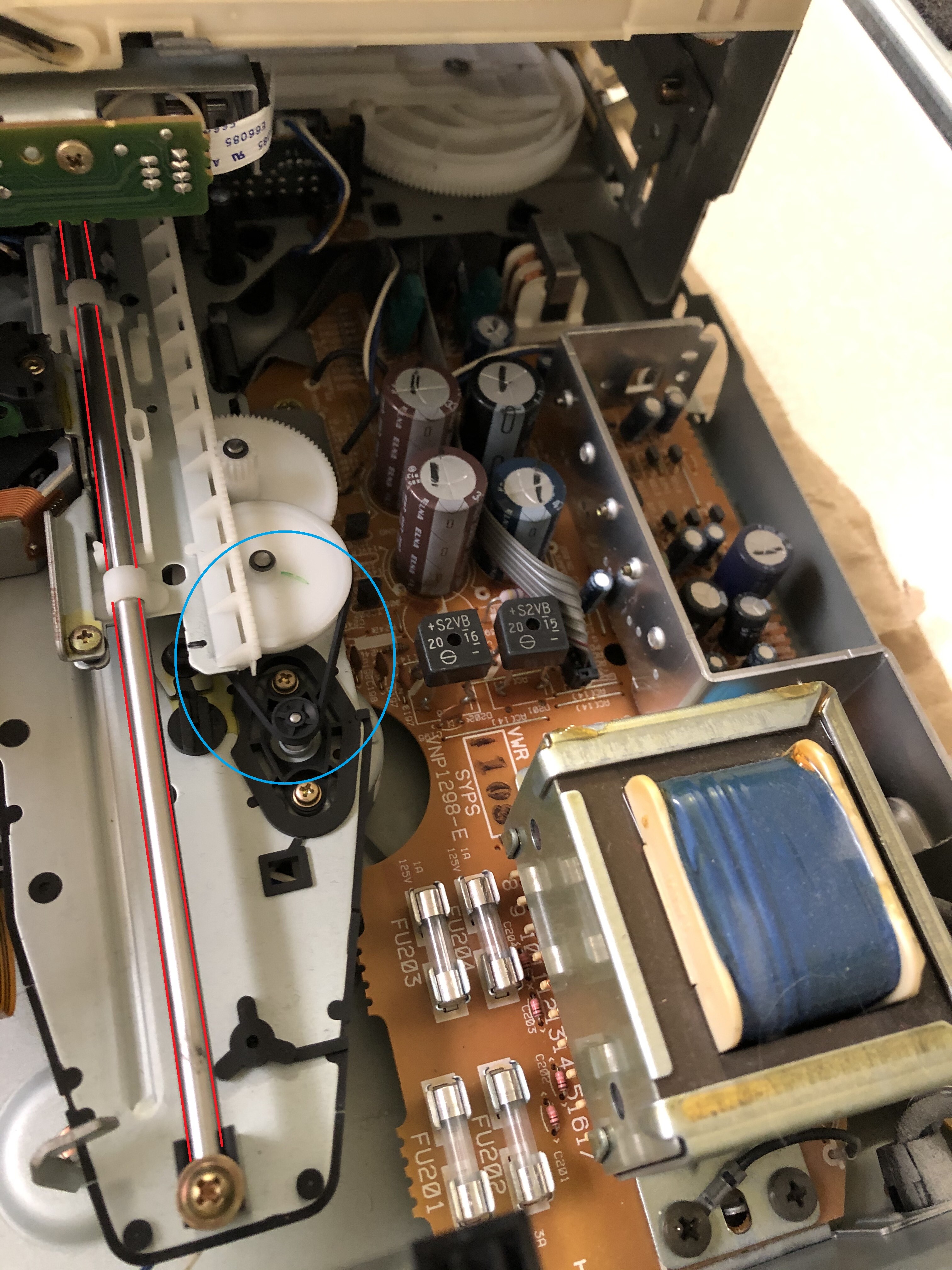
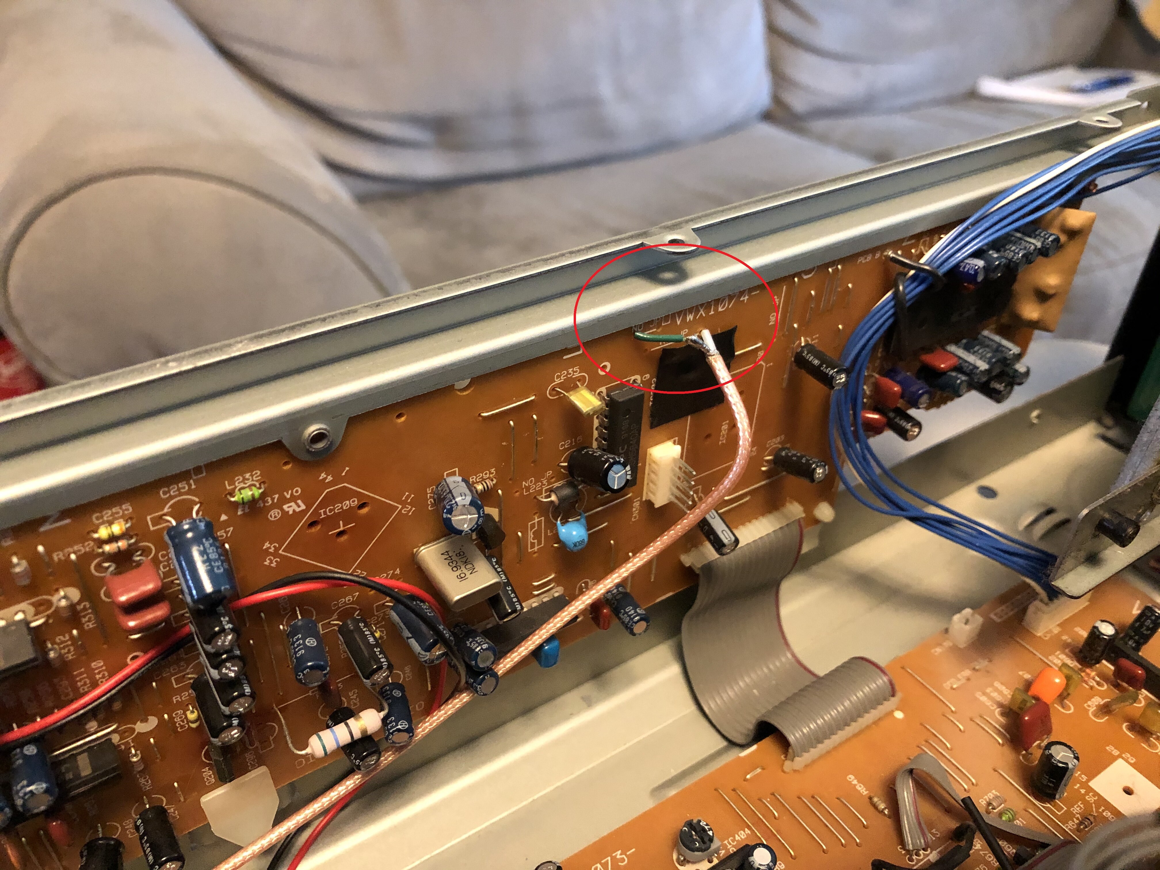
The AFM point is tapped from the audio board (hangs vertical on the right side of the player) off of the middle pin of transistor Q351 which is located right before the band pass filters of the CX chip.

I had my coax cable soldered from the other side as such and also had the shielding grounded via the green wire.
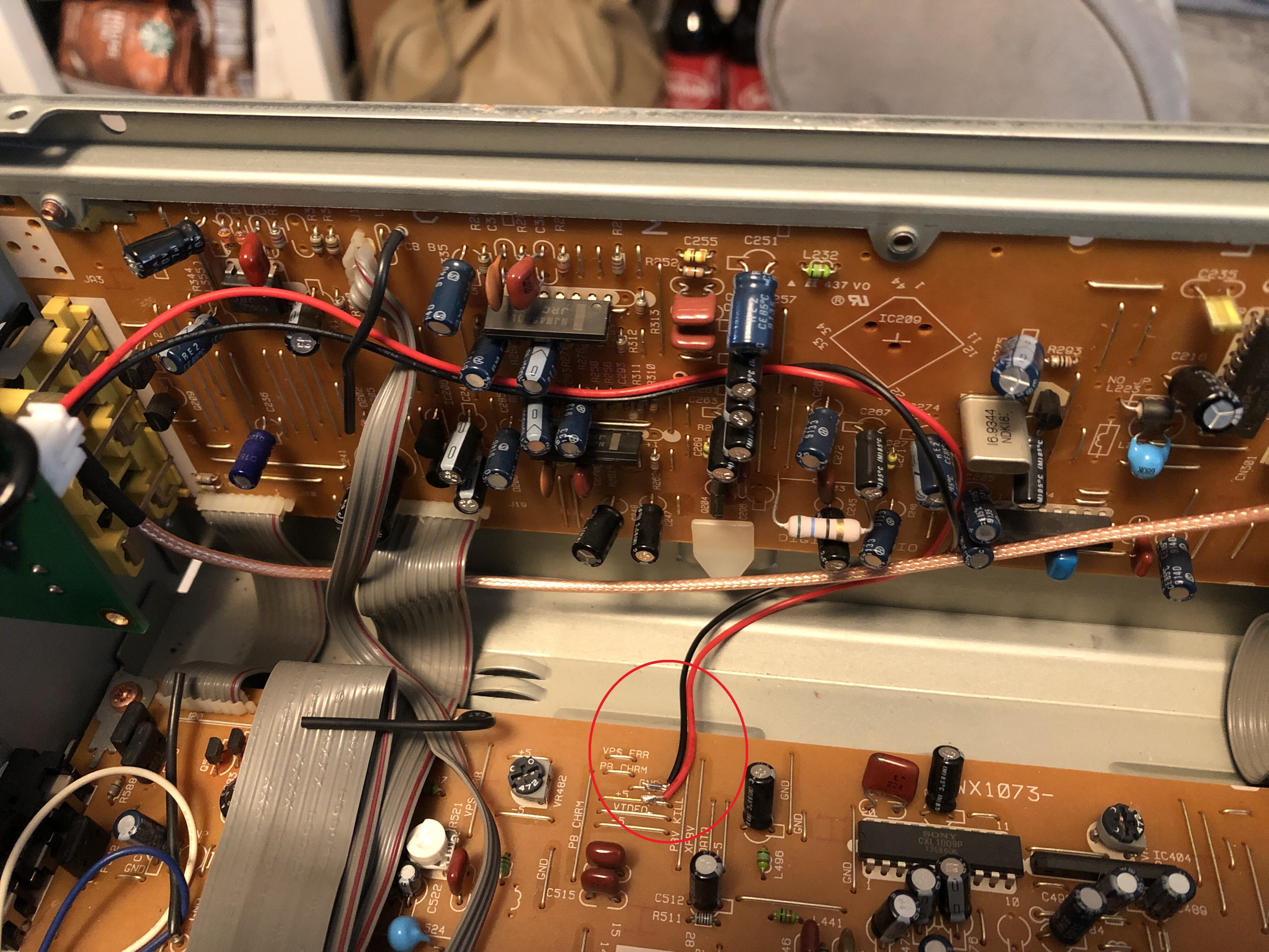
The remaining wires needed for the board are +5vdc (red), -5vdc (blue), Mute (yellow), GND (black), and another RF cable to the RCA jack. Here are images of all of them connected up.....
..... and the AC3-RF board w/ all the wires now connected.
Now a wide shot showing the entirety of the two mods.
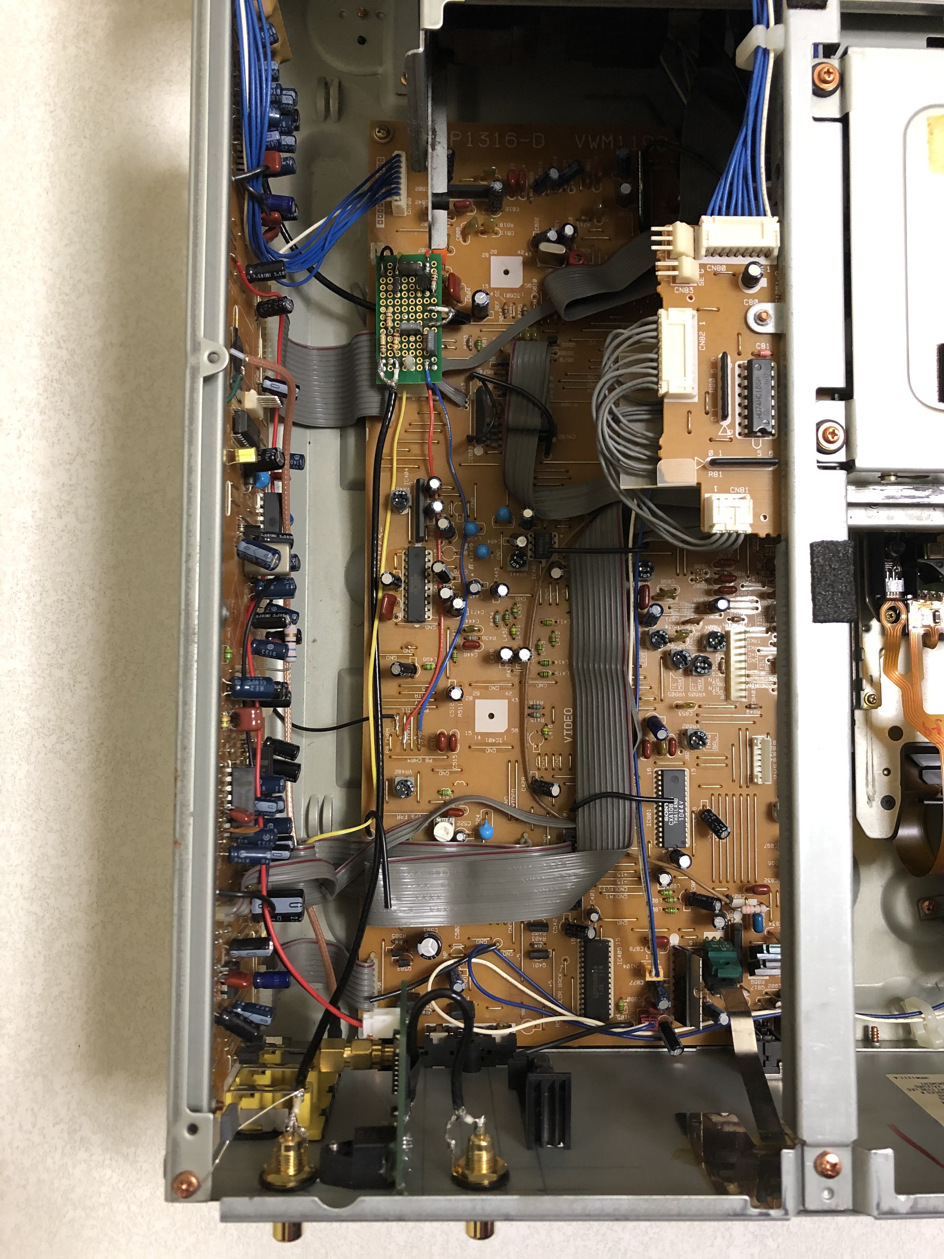
And finally, a shot of how much clearance there was w/ the tray. It looks close to hitting it but in reality there is still plenty of room.

I tested the board w/ an AC3 LD and confirmed the signal was passing to my Demodulator / Processor and I did get a voltage output on the RCA jack at around 4.3 volts w/ the mute control operating correctly to kill that power on pause and stop (I really do feel if anyone does this mod to really try and get your mute control to work as a means to prevent extraneous noise on your speakers during start up and side changes).
Adding Labels To The New Output JacksSo finally we're near the end and believe it or not this was somewhat a complicated mess. I originally wanted the Digital Outs to emphasize their use to transfer both PCM and DTS encoding but space between the jacks and my pickiness to maintain the font size made that difficult as you will see.
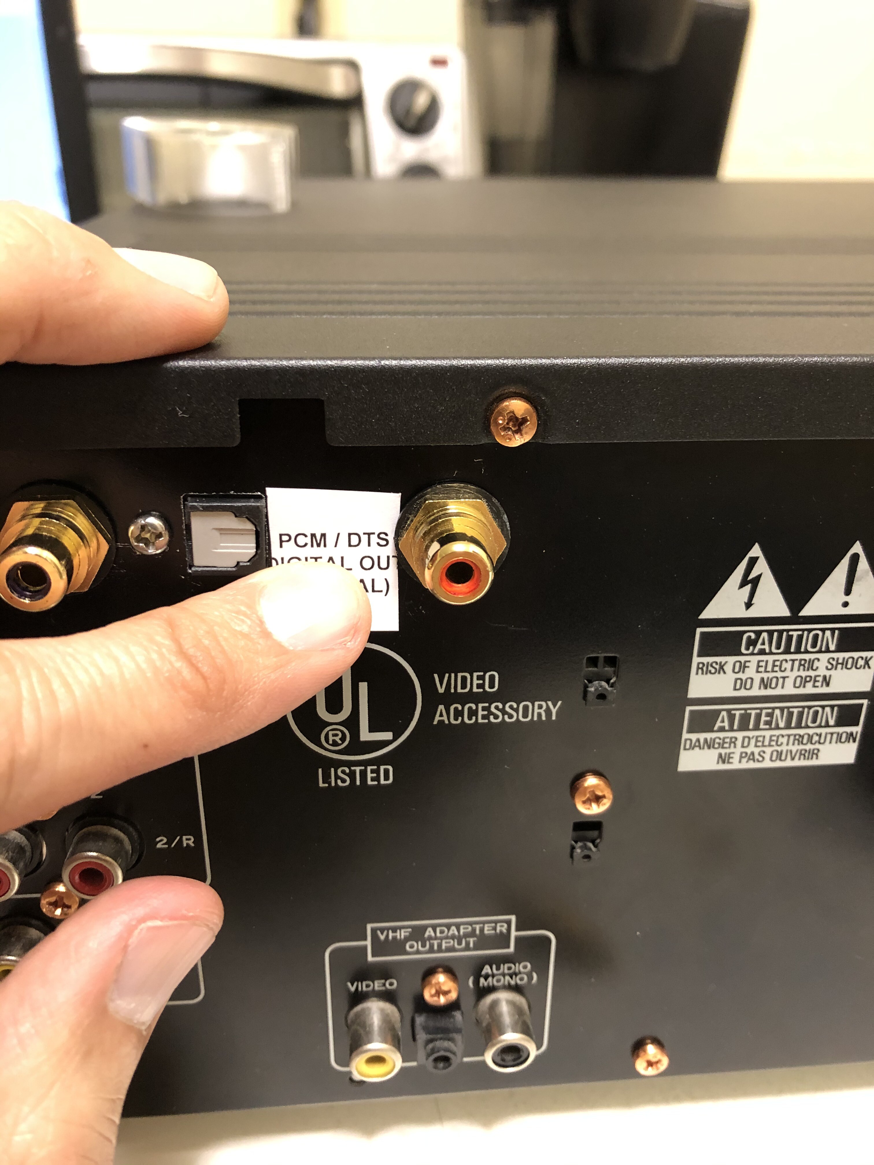
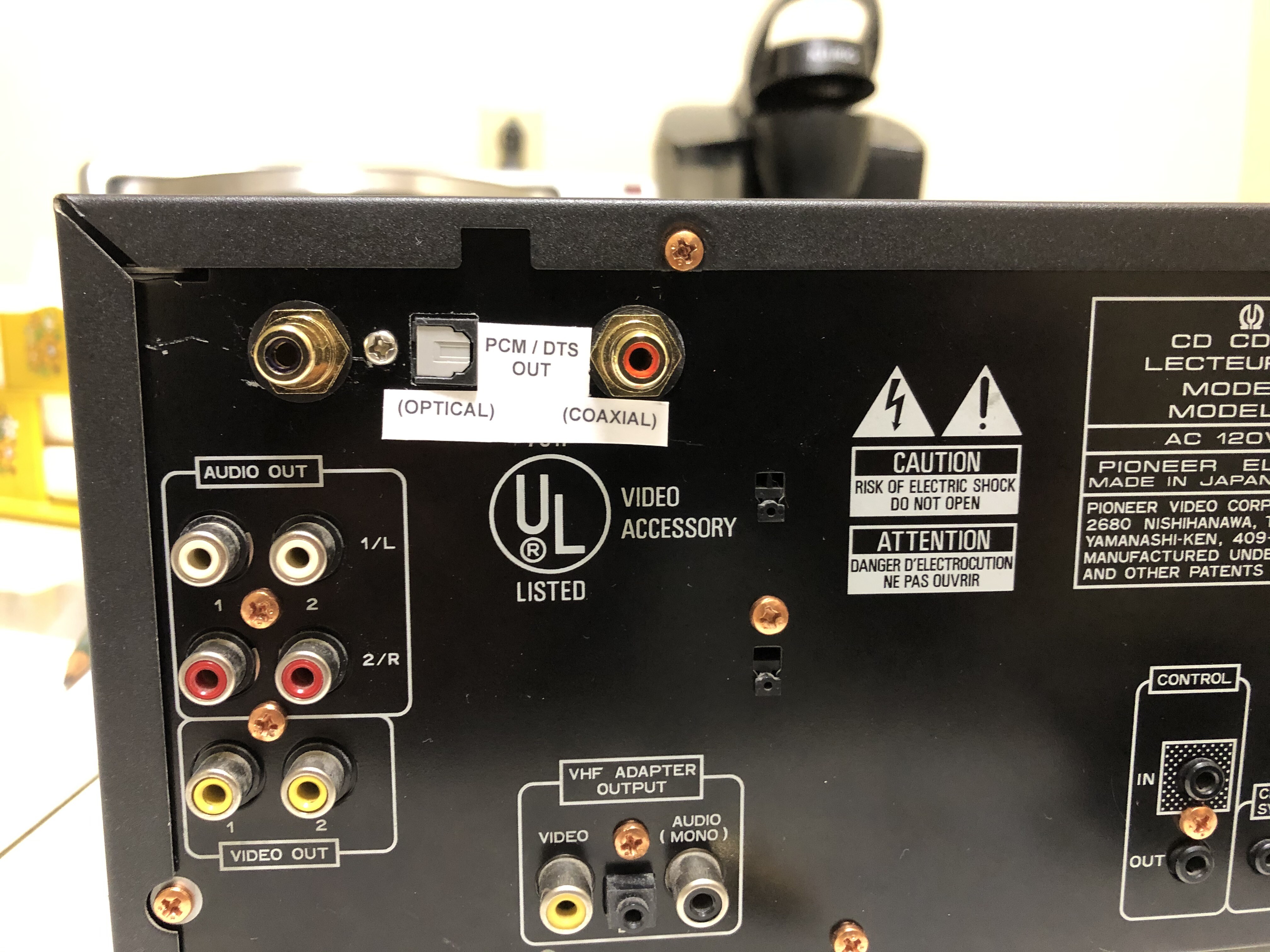
I ended up w/ the labeling you see @ the top of this post and overall I'm pretty happy with it. I was trying for all three labels to have the same height so they looked even across. Unfortunately, I think I made a total of four attempts to get it perfect and in the end I got tired of trying.
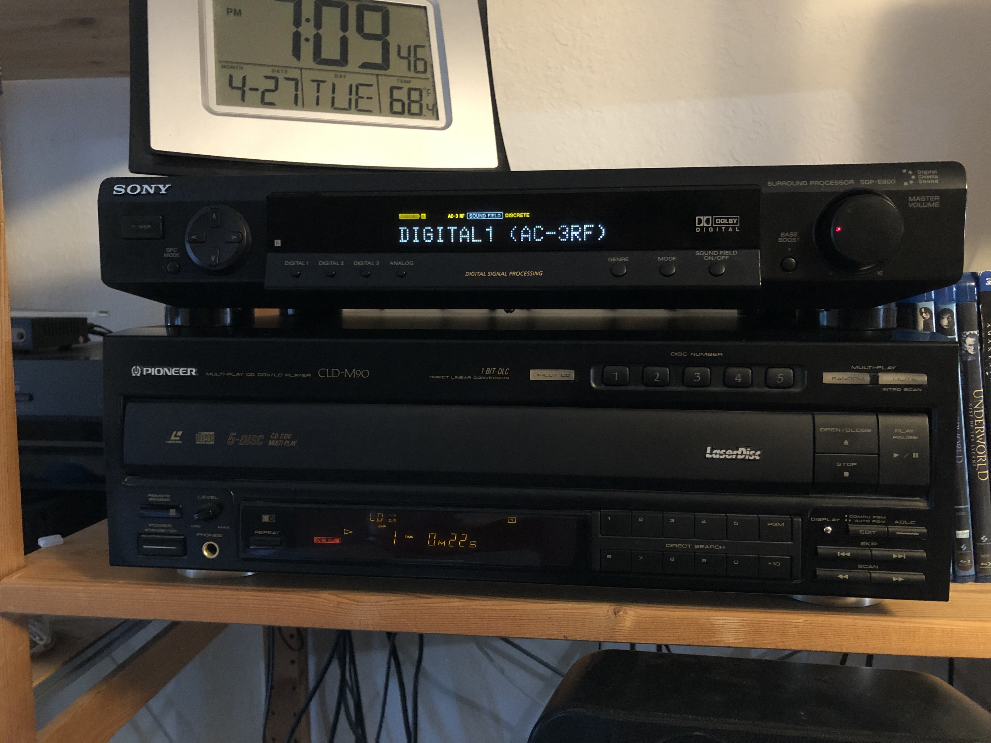
I had the player tested on AC3 & DTS LDs' and DTS CD. The mod worked as it should and it was thrilling knowing that I was listening to a sound codec that over a week ago the player was incapable of playing. And since it's a CD Changer as well, now I have the convenience of playing multiple DTS (or standard) CD titles without getting up from my seat (this is actually the only CD Changer I've ever owned). Picture quality wise, this player is definitely not impressive as it is a bit noisy but it still holds up fine (especially with discs that have good mastering). I'll be using this player soon on my cheap set-up so I can pull my ProScan out for some much delayed minor maintenance and further test the player.
Hope everyone enjoyed the post.