|
It is currently 26 Apr 2024, 15:08
|
View unsolved topics | View unanswered posts
 |
|
 |
|
| Author |
Message |
|
jamski68
|
Post subject: Re: CLD-2950 PALB Assembly / mod  Posted: 20 May 2016, 23:34 |
| Genuinely interested |
 |
 |
Joined: 28 Jul 2014, 15:28
Posts: 49
Location: United Kingdom
Has thanked: 1 time
Been thanked: 1 time
|
happycube wrote: Sounds like that's the video level - VR482 on the VDTB board adjusts that, and as long as that bit hasn't been bypassed that should fix it for you. I suspect the original adjustment expected a voltage dip, and didn't expect such a high quality output circuit.  If you can get a Pioneer test disk in Europe easily enough, that will help you get the levels correct since you can follow along with the adjustments in chapter 1 of the SM. Very helpful happycube! Will give that a go (hopefully this weekend) and let you know. I don't think we can order the test discs direct here in GB but there is a US site, partsimple.com which seems to have all the Pioneer parts. Are these guys any good? |
|

|
|
 |
|
jamski68
|
Post subject: Re: CLD-2950 PALB Assembly / mod Posted: 01 Jan 2019, 16:52 |
| Genuinely interested |
|
|
Joined: 28 Jul 2014, 15:28
Posts: 49
Location: United Kingdom
Has thanked: 1 time
Been thanked: 1 time
|
locutus2000 wrote: So I know this topic is old but I'm also unhappy about the ntsc playback. Will this chip change my life? Can someone share experience in installation? If you don't have a separate scaler I'd get one of the those first... My Sony TV doesn't handle NTSC properly and I'd image a lot of other UK / European market TVs will be the same... I'm using a DVDO VP50 which works well for Laserdiscs and retro consoles alike |
|
|
|
|
|
|
blindrezo
|
Post subject: Re: [CLD-2950] PALB Assembly/mod Posted: 04 Jan 2019, 13:40 |
| Shows curiousity |
 |
 |
Joined: 03 Jan 2019, 12:58
Posts: 21
Location: Portugal
Has thanked: 6 times
Been thanked: 5 times
|
|
Hi all, and Happy New Year!
I had been looking for a way to improve the video quality of my 2950, and had originally found the same YouTube video that jamski68 posted earlier, but was unable to find any other information until I found this forum post a few days ago.
Unfortunately, I'm not very good with making these types of modifications, nor do I have proper soldering tools for the job. I've spoken with my brother, as he has the proper tools and is comfortable doing this type of work, but he asked for instructions on what needs to be done. I think that making the AD829 chip should be fairly straight forward, using the PDF, but my brother specifically asked how to connect it to the LD player. We have no idea where it should connect. The YouTube video is for a different model, and it looks as if he has 7 cables coming out of the chip...? Very confusing...
@jamski68, would you be willing to share the details on required parts and how to get this connected to the player? I would greatly appreciate any help you could give!
|
|
|
|
|
|
|
locutus2000
|
Post subject: Re: [CLD-2950] PALB Assembly/mod Posted: 07 Jan 2019, 16:52 |
| Knows how to post |
 |
|
Joined: 05 Oct 2018, 19:58
Posts: 13
Location: Netherlands
Has thanked: 3 times
Been thanked: 1 time
|
jamski68 wrote: You take the video signal from pin 7 of J602 on the VDTB assy (see pic), you'll then want to cut or de-solder that lead of the ribbon cable that goes to the PALB / YCNR board as we are bypassing that (you could actually install a switch at this point if you wanted to switch back between stock and the mod) . You'll also want to de-solder the stock RCA socket and replace it with a good quality one to connect up to your new line driver, I would also terminate the the output close to the chip itself rather than on the socket to reduce change of oscillations.
The 5v rails can be taken directly from the main board, you'll see a +5v -5v and a GND that you can solder straight to. I bypassed these with some electrolytic capacitors on my strip board circuit
Let me know if you want any more info! No need to configure anything with an oscillator or other equipment to make sure video and audio are in sync? |
|
|
|
|
|
|
jamski68
|
Post subject: Re: [CLD-2950] PALB Assembly/mod Posted: 07 Jan 2019, 19:16 |
| Genuinely interested |
|
|
Joined: 28 Jul 2014, 15:28
Posts: 49
Location: United Kingdom
Has thanked: 1 time
Been thanked: 1 time
|
locutus2000 wrote: I would be very interested in seeing before and after screenshots of this mod to compare and decide if this is worth the effort. Have a look at the first page of this thread that will give you an idea, sorry I don't have any capture equipment so all i can do is take photos of the TV screen |
|
|
|
|
|
|
blindrezo
|
Post subject: Re: [CLD-2950] PALB Assembly/mod Posted: 11 Feb 2019, 20:45 |
| Shows curiousity |
|
|
Joined: 03 Jan 2019, 12:58
Posts: 21
Location: Portugal
Has thanked: 6 times
Been thanked: 5 times
|
miskia wrote: Hello,
About the laser disc test disc GGV1069, is it still available from Donberg ?
And about the service remote, GGF1067, what are your advices to have a good replica ?
Thank you I can't speak for the remote, but I did recently buy the disc from Donberg. I received it a few weeks ago. They may still have stock. |
|
|
|
|
|
|
blindrezo
|
Post subject: Re: [CLD-2950] PALB Assembly/mod Posted: 14 Feb 2019, 11:55 |
| Shows curiousity |
|
|
Joined: 03 Jan 2019, 12:58
Posts: 21
Location: Portugal
Has thanked: 6 times
Been thanked: 5 times
|
Got an update for you guys! Here's the work that was done last night: Here's the finished mod. As you can see, we used some really big overkill capacitors, but only because we couldn't find anything smaller (lol) We decided to use hole in that small bit of metal just above the mod board 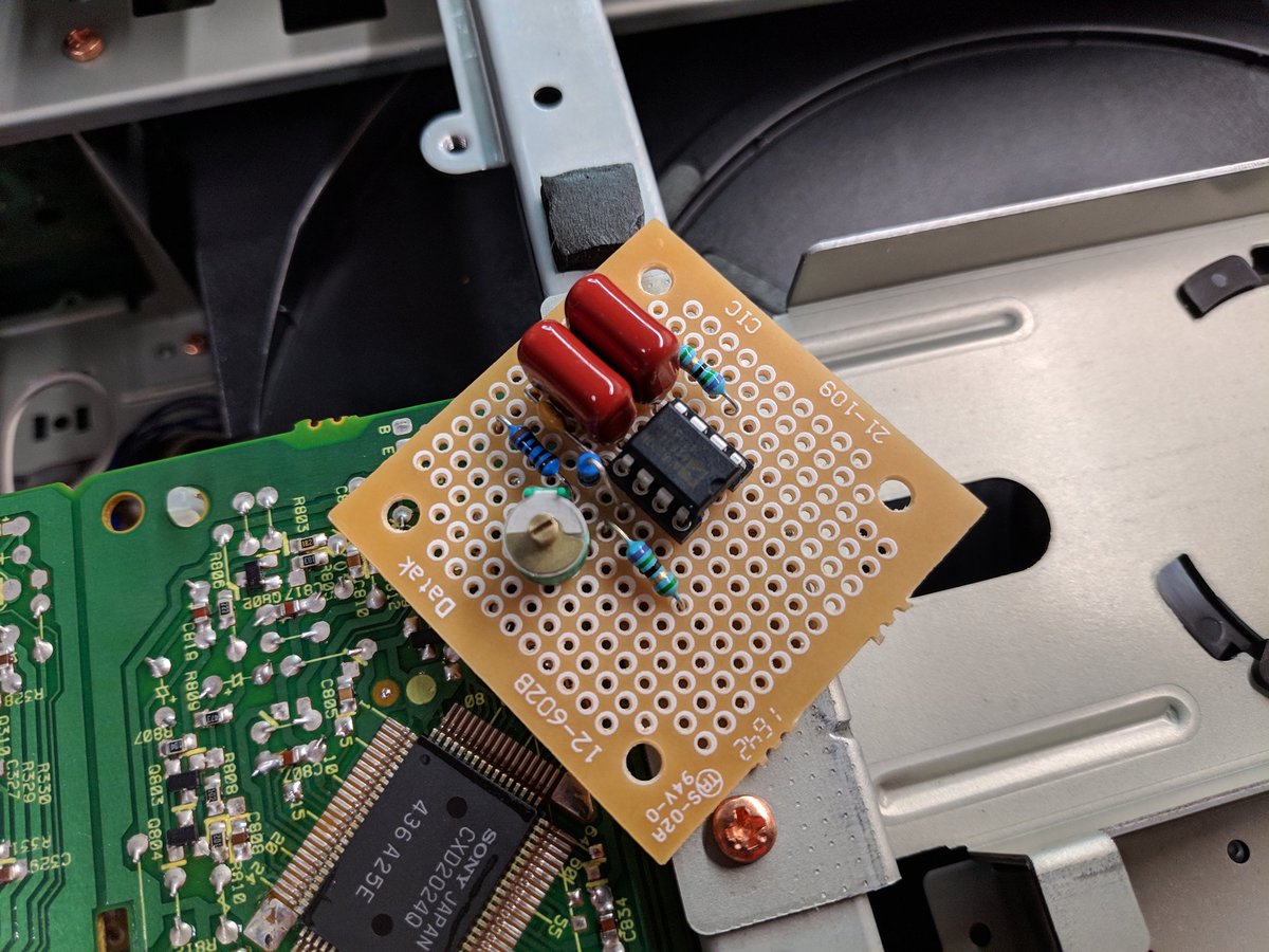 Here's a shot of it mounted - due to the oversized capacitors, we had to face it down 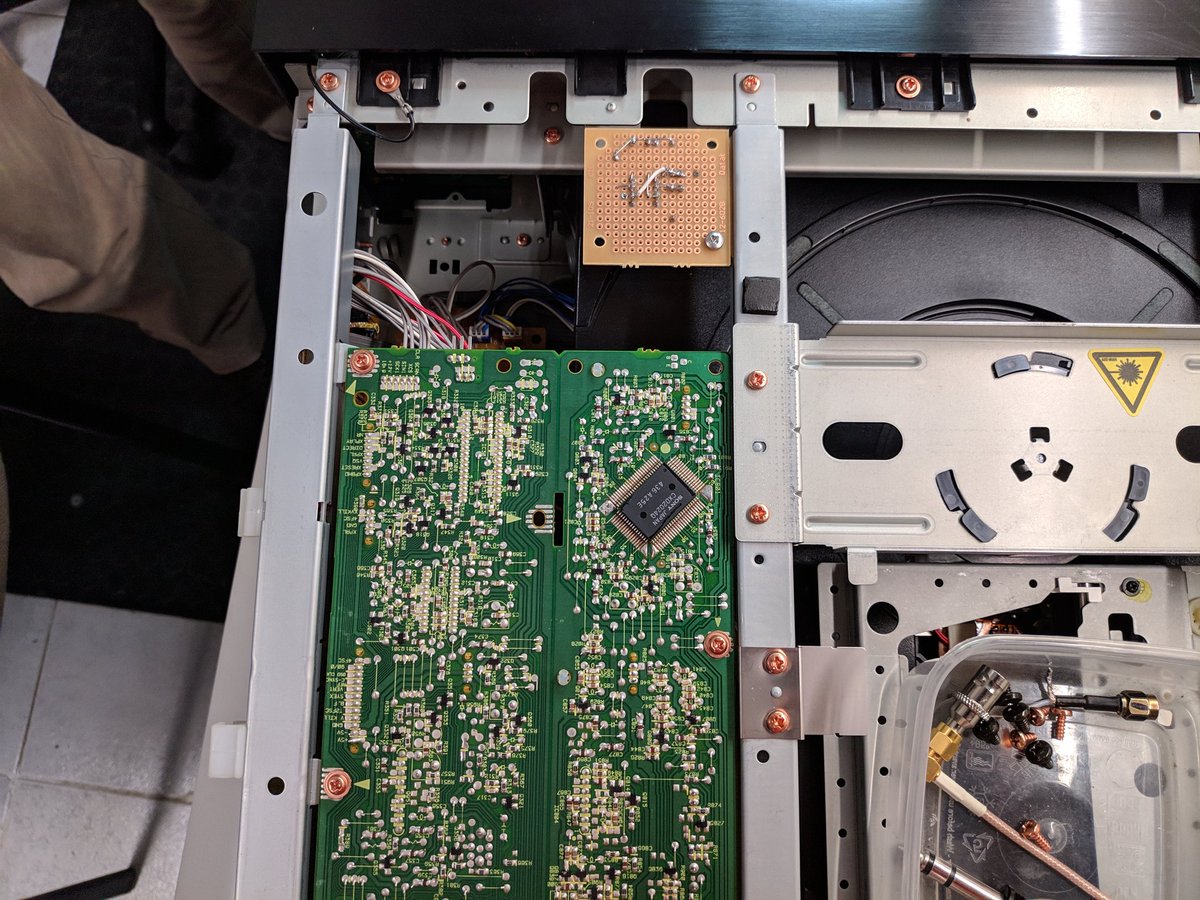 My colleague and his friend decided to pull everything directly off the board on top, as they said that the signal from there was electrically the same as the PALB board 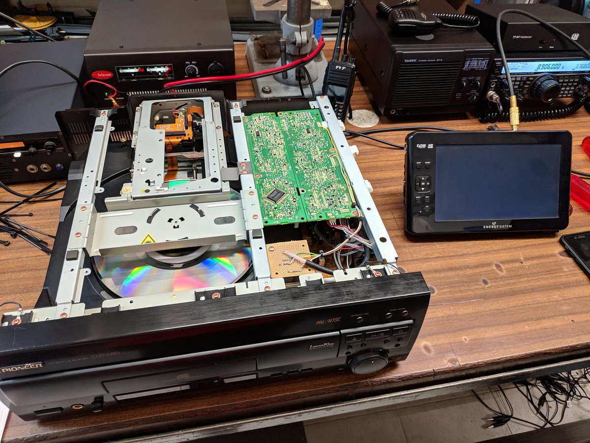 By the time we finished, it was already 1AM, so we didn't really have time to test much. When I got home, I tested it and believe I experienced the same issue as jamski68, due to the resistor on the input. The video was very dark. My colleague had told me that he wanted to follow the original diagram and that if we experienced the dark video, he would simply clip off the resistor. With luck, we'll be able to meet again tonight to clip off the resistor. We should then have ample time to properly test out and tweak things. I'll then get back to you guys with another update.  |
|
|
|
|
|
|
|
 |
|
 |
|
You cannot post new topics in this forum
You cannot reply to topics in this forum
You cannot edit your posts in this forum
You cannot delete your posts in this forum
You cannot post attachments in this forum
|
|


